5604 Input/Output (I/O) Module - Hardware Manual
October 19, 2007
6 Analog Outputs
The 5604 I/O Module may include two channels of analog output if this option was requested at
time of purchase.
For TelePACE applications use the SCADAPack AOUT I/O Module register assignment to
write to the two analog outputs.
For ISaGRAF applications use the aout2pt I/O connection to write to the two analog outputs.
Please refer to the respective TelePACE and ISaGRAF software manuals on how to assign the above
registers to read these input ports.
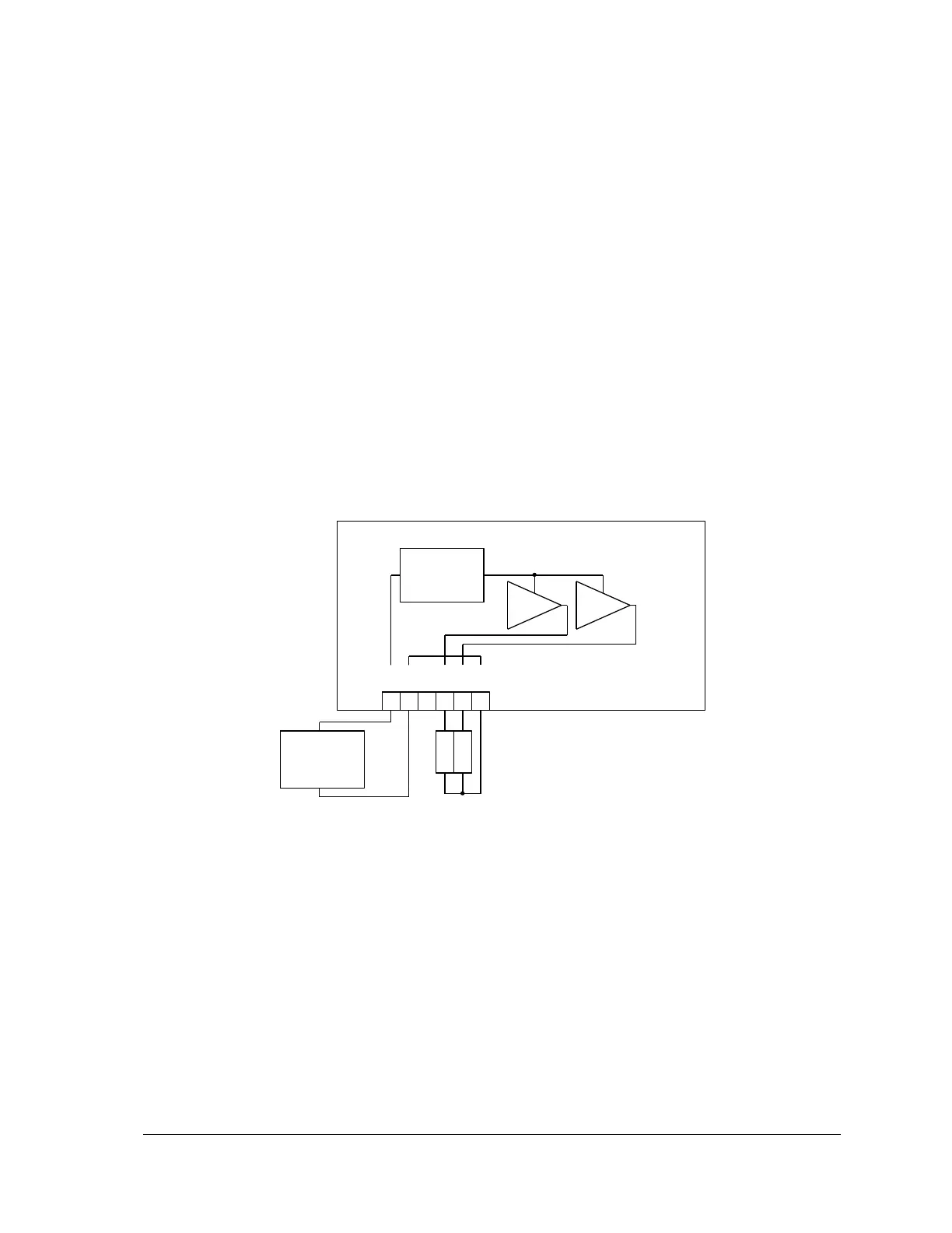
6.1 Current Outputs
The 5604 I/O Module can be equipped with an optional 5305 Analog Output Module that provides
two 20mA analog outputs. Analog output resolution is 12 bits. The outputs are transient and over
voltage protected. The outputs share a common return (GND) with each other and the 5604 I/O
Module analog inputs.
The 12V to 24V DC/DC boost converter powers the analog outputs. The boost converter is used to
boost the DC input power to 24V. The application program may control the boost converter.
+
External 12 or
24Vdc Power
Supply
_
P3 – Power and Analog Outputs
DC/DC
boost converter
24Vdc output
Figure 9: Analog Output Wiring