5604 Input/Output (I/O) Module - Hardware Manual
October 19, 2007
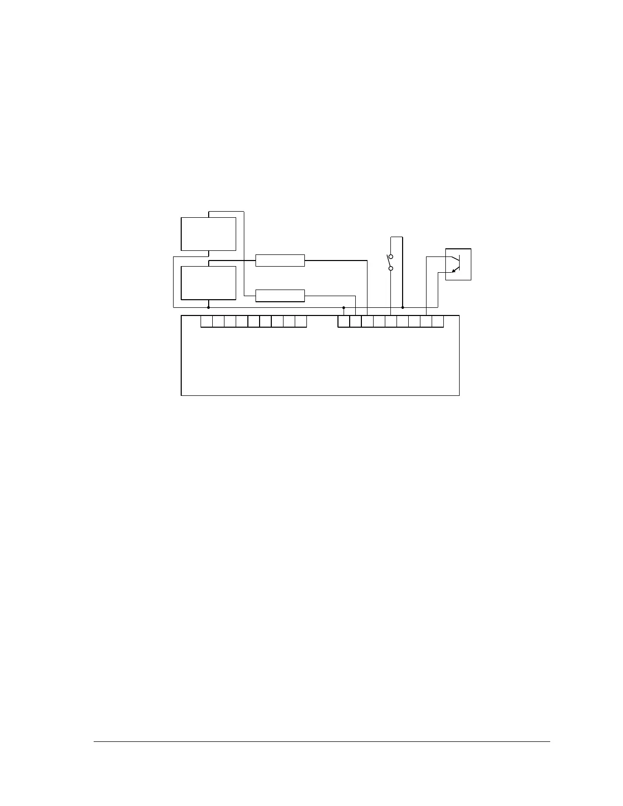
7.4 Wiring Examples
Various I/O point wiring examples are shown in Figure 10: Digital Input/ Output Wiring below.
Inputs and outputs can be used on any of the I/O points.
Digital I/O point 7 is shown connected to a 12V load and external 12V-power supply.
Digital I/O point 6 is shown connected to a 24V load and external 24V-power supply.
Digital I/O point 4 is shown monitoring a dry contact.
Digital I/O point 1 is shown monitoring an open collector contact.
P7 and P8 – Digital I/O 8-23 not shown.
GND 31 30 29 28 27 26 25 24
Figure 10: Digital Input/ Output Wiring