5604 Input/Output (I/O) Module - Hardware Manual
October 19, 2007
3 Field Wiring Connectors
The 5604 I/O modules use screw termination style connectors for termination of field wiring. These
connectors accommodate solid or stranded wires from 12 to 22 AWG.
CAUTION: Remove power before servicing unit.
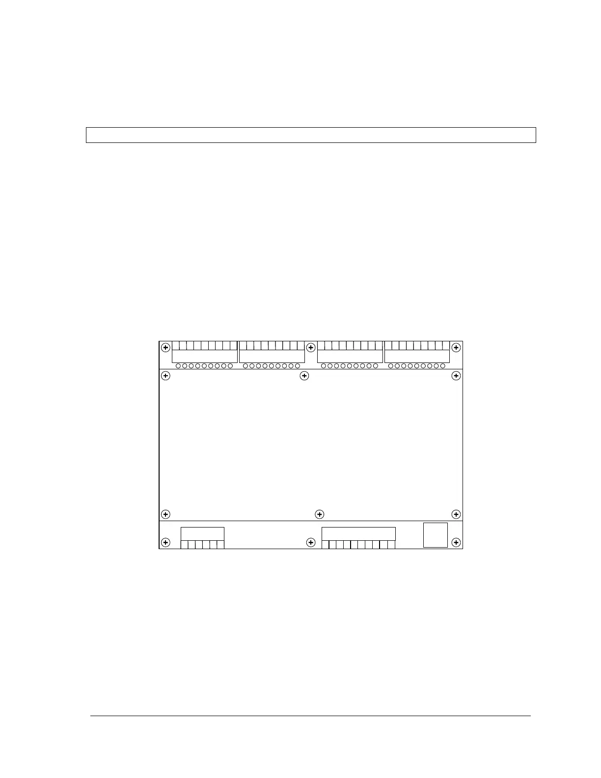
The 5604 I/O module has seven connectors for field wiring. Refer to Figure 1: 5604 I/O Module
Layout for connector locations.
Primary power input connections, VLOOP output power connection and optional analog output
connections are wired to a six-pole connector labeled P3. Refer to section 4-Power Supply for
details on wiring the power supply.
The nine analog inputs are wired to a ten-pole connector labeled P4. Refer to section 5-Analog
Inputs for details on wiring analog input signals.
The digital inputs and outputs are wired to four ten-pole connectors labeled P6, P7, P8 and P9.
Refer to section 7-Digital I/O for details on wiring digital input/output signals.
The 5604 I/O Module has one RS-232 serial communication port that is wired to a black 8 pin
modular RJ-45 connector labeled P5. Refer to section 8-Serial Communication for details.
Digital I/O 24-31
Connector (P6)
Digital I/O 16-23
Connector (P7)
Digital I/O 8-15
Connector (P8)
Digital I/O 0-7
Connector (P9)
Power – Analog Out
Connector (P3)
Analog Inputs
Connector (P4)
RS-232 COM3
Connector (P5)
Figure 1: 5604 I/O Module Layout