5604 Input/Output (I/O) Module - Hardware Manual
October 19, 2007
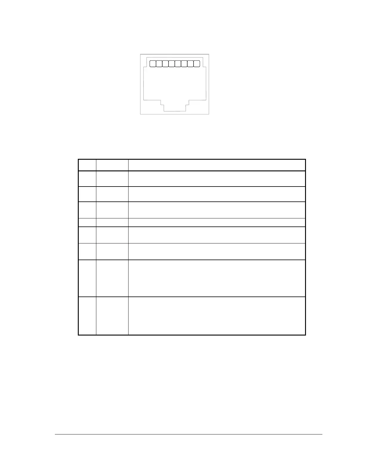
1. +5V
2. DCD
3. DTR
4. GND
5. RxD
6. TxD
7. CTS
8. RTS
Figure 11: Front View of an RJ-45 Connector
The following table provides a description of the function of each pin of the RJ-45 connector. In this
table a MARK level is a voltage of +3V or greater and a SPACE level is a voltage of –3V or less.
This pin can be connected to the 5V power supply by installing a
jumper at J4 on the SCADAPack controller board.
The DCD led is on for a MARK level.
This pin is normally at a MARK level.
This pin is at a SPACE level when DTR is de-asserted.
This pin is connected to the system ground.
The level is SPACE on standby and MARK for received data.
The LED is lit for a MARK level.
The level is SPACE on standby and MARK for transmitted data.
The LED is lit for a MARK level.
This level must be a MARK for the communication port to
transmit data. When the attached device does not provide this
signal, the controller keeps the line at a MARK.
When the attached device does provide this signal, it must set
CTS to MARK to allow the controller to transmit data.
This pin is a MARK if full-duplex operation is selected for the
port.
This pin is set to a MARK just before and during transmission of
data if half-duplex operation is selected.
This pin is set to a SPACE when no data is being transmitted.
8.3 RS-232 Wiring Examples
See the chapter on Serial Communications in the hardware manual of your respective controller
board for wiring examples.
8.4 RS-232 Cables
8.4.1 RJ-45 to DE-9S DTE
This cable is used to connect from an RJ-45 based RS-232 port on the 5604 I/O module to a DE-9P
connector on a DTE such as a PC. A 10 ft. long cable is available from Control Microsystems as
part number 297217.