5604 Input/Output (I/O) Module - Hardware Manual
October 19, 2007
4.2.4 Recommended 5103 Power Supply Configuration
When additional power is required by the system, 5000 Series 5103 power supplies can be used in
combination with the SCADAPack controllers. Refer to the System Configuration Guide for more
information.
The 5103 power supplies can be connected anywhere downstream (to the right) of the controller.
They will supply power to the modules downstream of them.
Note: The Sleep Mode feature of the controller applies only to those modules powered by the
controller.
The 5103 power supply may also be connected upstream (to the left) of any SCADAPack
Controller, but only if the following conditions are observed:
No power is applied to the power inputs of the controller board.
A jumper is installed at position J5 (see the user manual of your respective controller board for
details.
The sleep mode feature is not used.
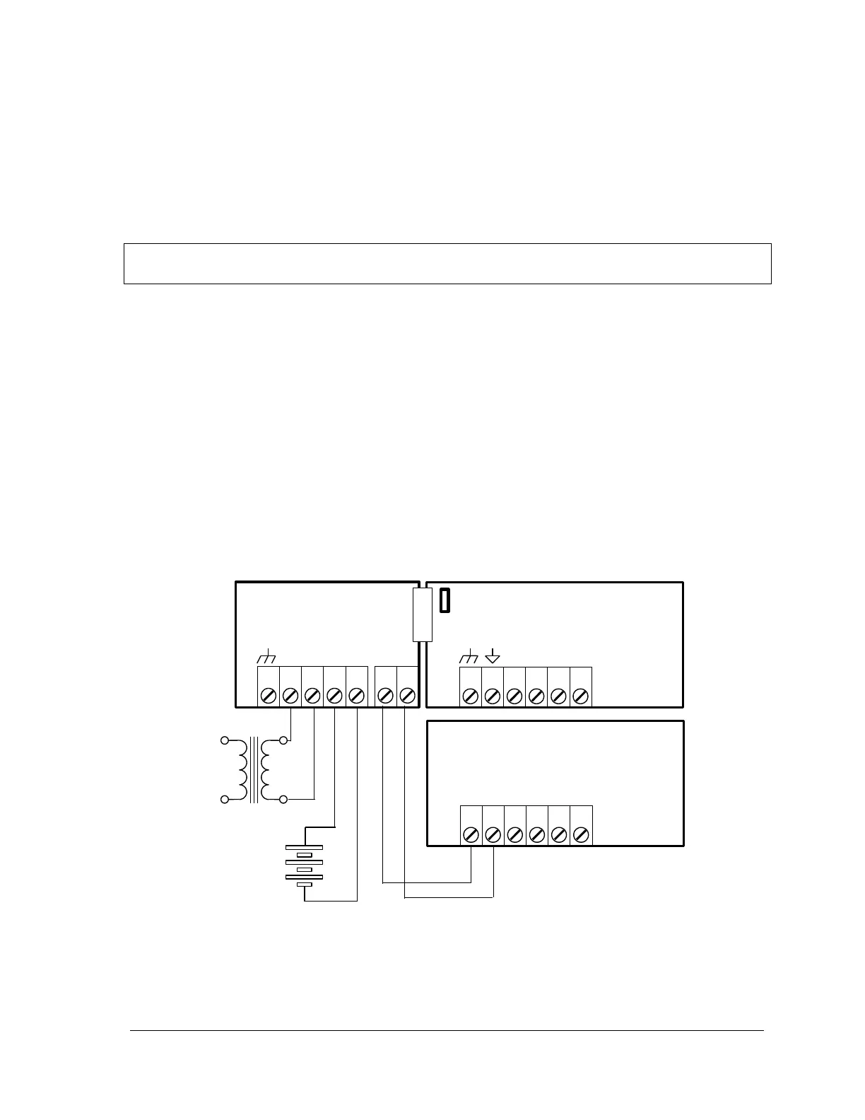
This configuration uses a 5103 Power Supply module to power a SCADAPack controller. The
24VDC output from the 5103 powers the 5604 I/O module. The 5103 power supply provides a 5V
output to power the 5604 I/O module, the controller board and 5000 Series modules through the
IMC cables.
Note that no connection is made to the AC/DC PWR IN or DC PWR terminals on the controller
board.
Optional 12 Volt
Gel Cel Battery
Figure 5: Recommended 5103 Power Supply Configuration