5604 Input/Output (I/O) Module - Hardware Manual
October 19, 2007
4.3 System Grounding
In most applications, it is desirable to ground the system by connecting the system power supply
common, to the chassis or panel ground.
On the 5604 I/O module, “-“ terminal of the 24V supply(DC PWR “-“) is already connected to the
enclosure by the printed circuit board traces.
4.4 Power Management Features
The 5604 I/O board provides a number of special features to reduce power consumption. These
power management features include:
VLoop power control.
12V to 24V DC/DC Converter Control.
The 5604 I/O module provides two internal digital outputs that can be operated by the user
application to manage the power saving features. Internal digital outputs 32 and 33 and the power
management functions they control are described in the following sections.
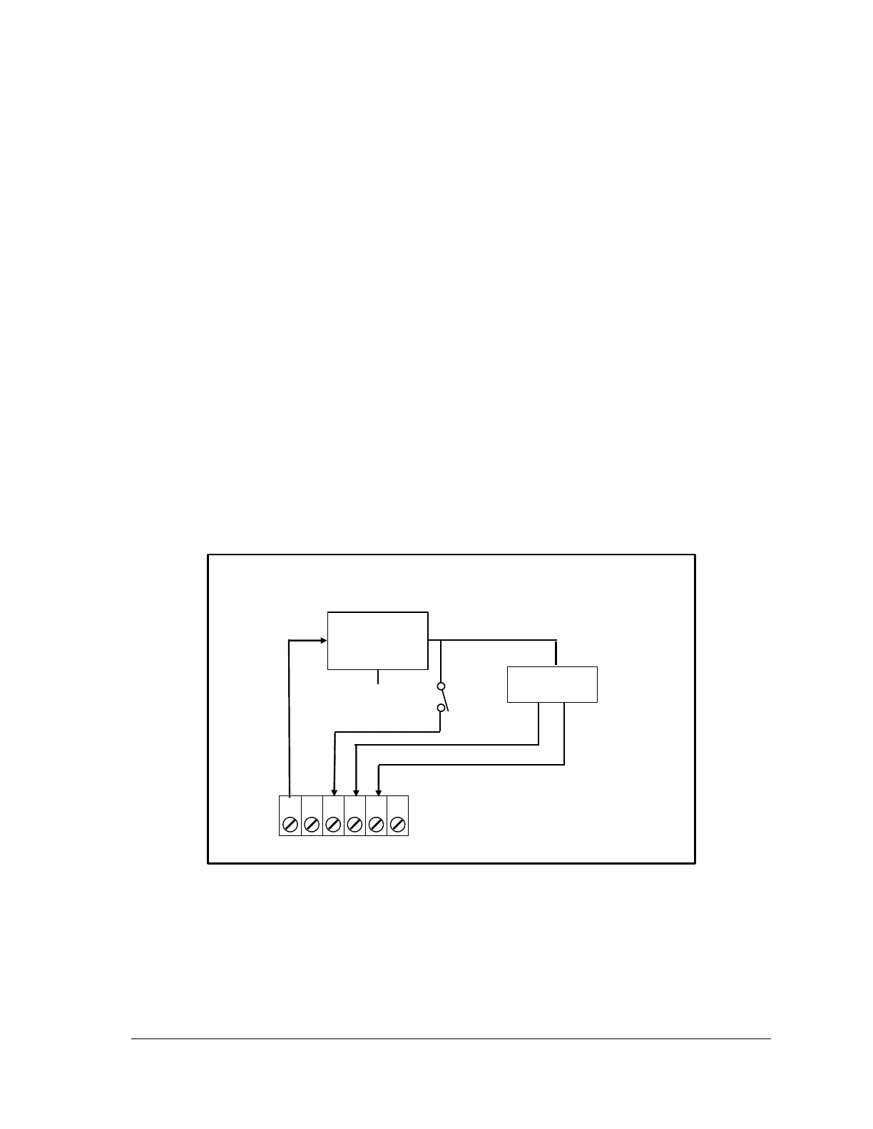
Refer to Figure 6: Power Management for an overview of the power management features. Refer
to the appropriate software manual for information on using and controlling the internal Digital
Outputs. For TelePACE applications refer to the Register Assignment for the SCADAPack 5604 I/O
module and for ISaGRAF applications refer to the I/O Complex Equipment for SCADAPack 5604
I/O module.
5305 Analog
Output Module
Figure 6: Power Management
4.4.1 DC/DC Converter Control
The 12V to 24V DC/DC converter is used to provide 24 VDC for VLoop power and for the Analog
Output module. The converter should be turned on if the 5604 I/O Module is equipped with analog