+5V is only available on Pin 1 when a jumper is installed on J4.
Serial port COM1 may be configured as RS-232 or RS-485. A jumper must be installed on J9 to
operate COM1 in RS-485 mode. Refer to the Figure 1: 5232 Controller Board Layout for the
location of jumpers J4 and J9.
The differential receive and transmit signals are labeled +/–Rx and +/–Tx respectively. Some RS-485
devices refer to the – side of the signal as A and the + side of the signal as B.
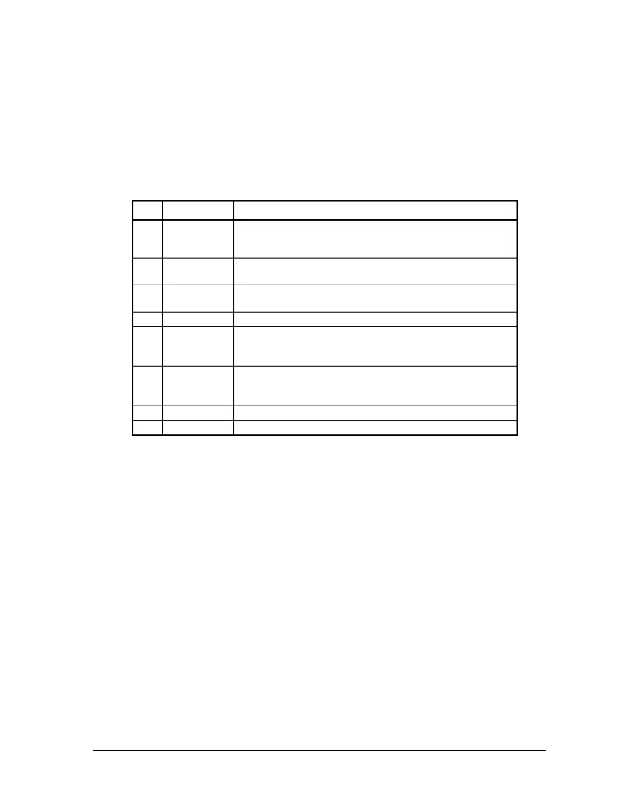
The following table provides a description of the function of each pin of the RJ-45 connector. In this
table a MARK level is a voltage of +3V or greater and a SPACE level is a voltage of –3V or less.
Pin Function Description
1 5V
(Output)
This pin can be connected to the 5V power supply by
installing a jumper at J4 on the SCADAPack controller
board.
2 -Rx
(Input)
The DCD led is on for a MARK level.
3 -Tx
(Output)
This pin is normally at a MARK level.
This pin is at a SPACE level when DTR is de-asserted.
4 GND This pin is connected to the system ground.
5 +Rx
(Input)
The level is SPACE on standby and MARK for received
data.
The LED is lit for a MARK level.
6 +Tx
(Output)
The level is SPACE on standby and MARK for transmitted
data.
The LED is lit for a MARK level.
7 N/C Do not connect this pin for RS-485 operation.
8 N/C Do not connect this pin for RS-485 operation.
9.6.2 RS-485 Bias Resistors
The RS-485 receiver inputs on the SCADAPack 32 controller are biased to ensure that that received
data is driven to a valid state (space) when there are no active drivers on the network. The value of
these bias resistors is 4700 ohms from Ground to the –Rx input and 4700 ohms from +5V to the +Rx
input.
9.6.3 RS-485 Termination Resistors
Termination resistors are required in long networks operating at the highest baud rates. Shorter
networks in high noise environments may also benefit from terminations. Networks as long 1000 ft.
operating at 9600 baud will function without termination resistors. Terminations should be
considered if the baud rate is higher and the network is longer.
When termination resistors are required, they are installed on the first and last station on the RS-485
wire pair. All other stations should not have termination resistors.
RS-485 networks are generally terminated with 120-ohm resistors on each end. The required 120-
ohm resistor is built into the SCADAPack 32 controller. When these termination resistors are used,
the biasing generally has to be increased in order to generate at least 0.2V across the +/–Rx input.
To connect the termination resistors:
• Install a jumper across J8 to terminate the Rx pair.
SCADAPack 32 Controller Hardware Manual
May 24, 2006
32