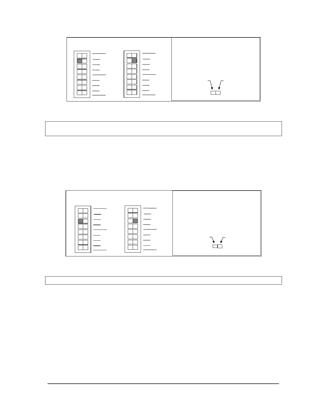
Slide the actuator
this side for
4-20mA
Slide the actuator
to this side for
0-20mA
How to Set the Range Switch:
•
Determine the desired range.
•
Slide the actuator to the side of
the switch shown in gray.
4-20mA Outputs
0-20mA Outputs
SW 1
2
1
2
3
4
0
1
not used
Options
Filters
SW 1
2
1
2
3
4
0
1
not used
Options
Filters
Figure 21: Analog Output Offset DIP Switches.
Note:
The default setting for the optional analog outputs is the 0% offset with output signals
ranging from 0-20mA in current mode or 0-5V in voltage mode.
11.6 Line Frequency Selection
The SCADAPack controller may select a 50 or 60 Hz line frequency for digital and analog input
processing. Switch ‘Options 3’ on SW1 selects this option. On the SCADAPack P4 or P4A, press the
left side of dip switch as shown in the figure below to select the 60Hz line frequency and the other
side of the switch to select the 50Hz line frequency. On the SCADAPack P4B, select these settings
when via software as the 5606 I/O section of the manual.
This side for
50Hz.
This side for
60 Hz.
How to Set the Frequency Switch:
•
Determine the desired range.
•
Slide the actuator to the side of
the switch shown in gray.
60 Hz Operation
SW 1
2
1
2
3
4
0
1
not used
Options
Filters
SW 1
2
1
2
3
4
0
1
not used
Options
Filters
50 Hz O
eration
Figure 22: Line Frequency DIP Switches.
Note:
The 60Hz line frequency is enabled by default.
11.6.1 Digital Input Filters
Each of the three digital / counter (DIN/Counters) inputs on the SCADAPack 32 controller board can
be filtered. Filtering limits the maximum digital input or counter frequency to approximately 30Hz.
• Use a filter for 50 or 60Hz digital inputs and for low speed counting applications that experience
problems due to contact bounce.
• Do not use filtering for high speed counting applications.
SCADAPack 32 controller board SW1, switches Filter 0, Filter 1 and Filter 2 switches control the
input filter functions.
• Filter 0 for DIN/Counters input 0.
SCADAPack 32 Controller Hardware Manual
May 24, 2006
45