11.5.1 Analog Input Range Selection
The analog input channels on the integrated I/O modules on some versions of the SCADAPack 32
controller can be configured for a 0% or 20% offset using switch ‘Options 1’ on SW1. With the 0%
offset, the input signal measurement range is 0-20mA in current mode or 0-5V in voltage mode.
With the 20% offset, the input signal measurement range is 4-20mA in current mode or 1-5V in
voltage mode.
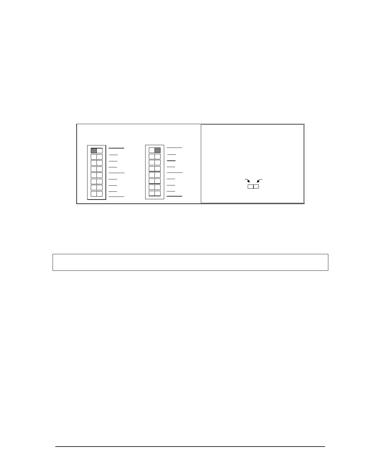
On the SCADAPack P4 equipped with the 5601 I/O board, select the 0% offset by sliding switch
‘Options 1’ on SW1 to the left as shown in the figure below. Select the 20% offset by sliding the
switch to the right.
Slide the actuator
to this side for
4-20mA or 1-5V
Slide the actuator
to this side for
0-20mA or 0-5V
How to Set the Range Switch:
•
Determine the desired range.
•
Slide the actuator to the side of
the switch shown in gray.
0-20mA or 0-5V
In
uts
SW 1
2
1
2
3
4
0
1
not used
Options
Filters
SW 1
2
1
2
3
4
0
1
not used
Options
Filters
4-20mA or 1-5V
In
uts
Figure 20: Analog Input Offset DIP Switches.
This option is not available on the SCADAPack P4A controller with the 5604 I/O module. On the
SCADAPack P4B controller with the 5606 I/O module, the settings are selected in software. See the
5606 Input-Output Module hardware manuals for details.
Note: The default setting for the analog inputs on the SCADAPack P4 and P4B is 0% offset or a
measurement ranges of 0-20mA in current mode or 0-5V in voltage mode.
11.5.2 Analog Output Range Selection
The optional analog output channels of the integrated I/O modules on the SCADAPack 32 controller
can be configured for a 0% or 20% offset using switch ‘Options 2’ on SW1. With the 0% offset, the
output signal ranges from 0-20mA in current mode or 0-5V in voltage mode. With the 20% offset,
the output signal ranges from 4-20mA in current mode or 1-5V in voltage mode.
On the SCADAPack P4 and P4A controllers respectively equipped with the 5601 and 5604 I/O
modules, select the 0% offset by sliding switch ‘Options 2’ on SW1 to the left as shown in the figure
below. Select the 20% offset by sliding the switch to the right. On the SCADAPack P4B the settings
are selected in software. See the 5606 Input-Output Module hardware manual for details.
SCADAPack 32 Controller Hardware Manual
May 24, 2006
44