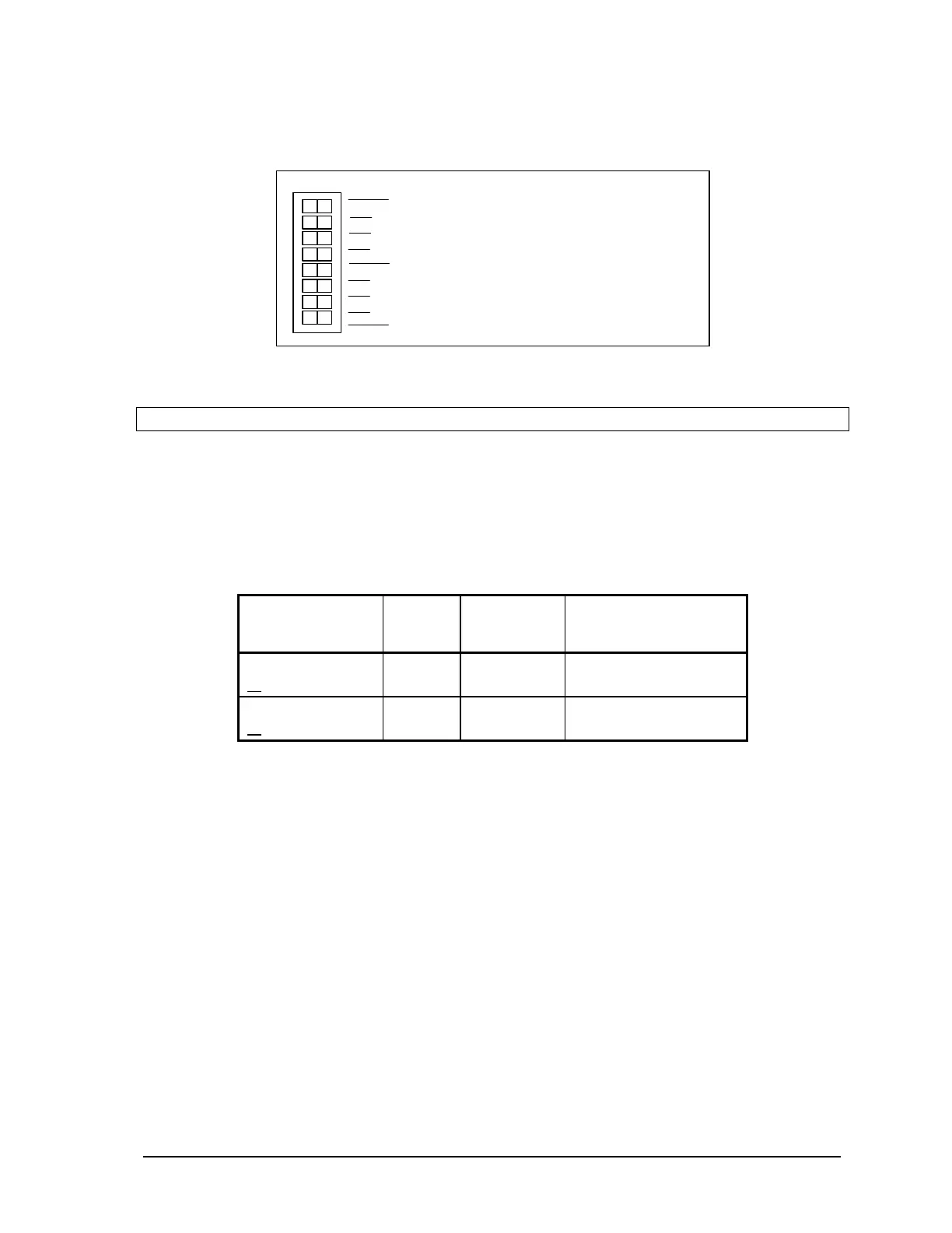
• Filter 1 for DIN/Counters input 1.
• Filter 2 for DIN/Counters input 2.
SW 1
2
1
2
3
4
0
1
not used
Options
Filters
•
To enable a filter, slide the Filter 0, Filter 1
or Filter 2 actuator to the right side of the
sw i tch (cl osed).
•
To disable a filter, slide the Filter 0, Filter 1
or Filter 2 actuator to the left side of the
switch (closed).
Figure 23: Low Pass Filter DIP Switches.
Note:
Filters are disabled by default.
11.7 5000 Series Analog Input Module Compatibility
5000 Series analog input modules 5501 and 5521 require firmware release D (or more recent), if they
are used with a controller board with a firmware release 1.23 (or more recent). The older 5501 or
5521 Series I/O module firmware must be upgraded otherwise incorrect data may be returned from
the module. Check the version of the firmware in your 5501 or 5521 analog input module against the
table below.
Check These
Parts
Part
Number
Chip
Location
Revision
Required
5501 firmware
or
160246
160303
U12
U12
Must be suffix D or later
Must be suffix A or later
5521 firmware
or
160246
160303
U12
U12
Must be suffix D or later
Must be suffix A or later
SCADAPack 32 Controller Hardware Manual
May 24, 2006
46