12 FXM5 User Guide
www.controltechniques.com Issue Number: 5
Digital control can be obtained only by connecting a Control Techniques Mentor II Drive
to PL1 of the FXM5 controller using the 10-way ribbon cable supplied with the controller.
When the cable is connected, the FXM5 control circuits are automatically disconnected
from the thyristor bridge driver N5; The Mentor II Drive then controls the bridge driver
directly.
Use Menu-6 parameters in the Mentor II Drive to set up and control the FXM5 controller.
Remove the following jumpers from the power boards of the Mentor II Drive:
3.9.3 Connections to the Mentor Drive
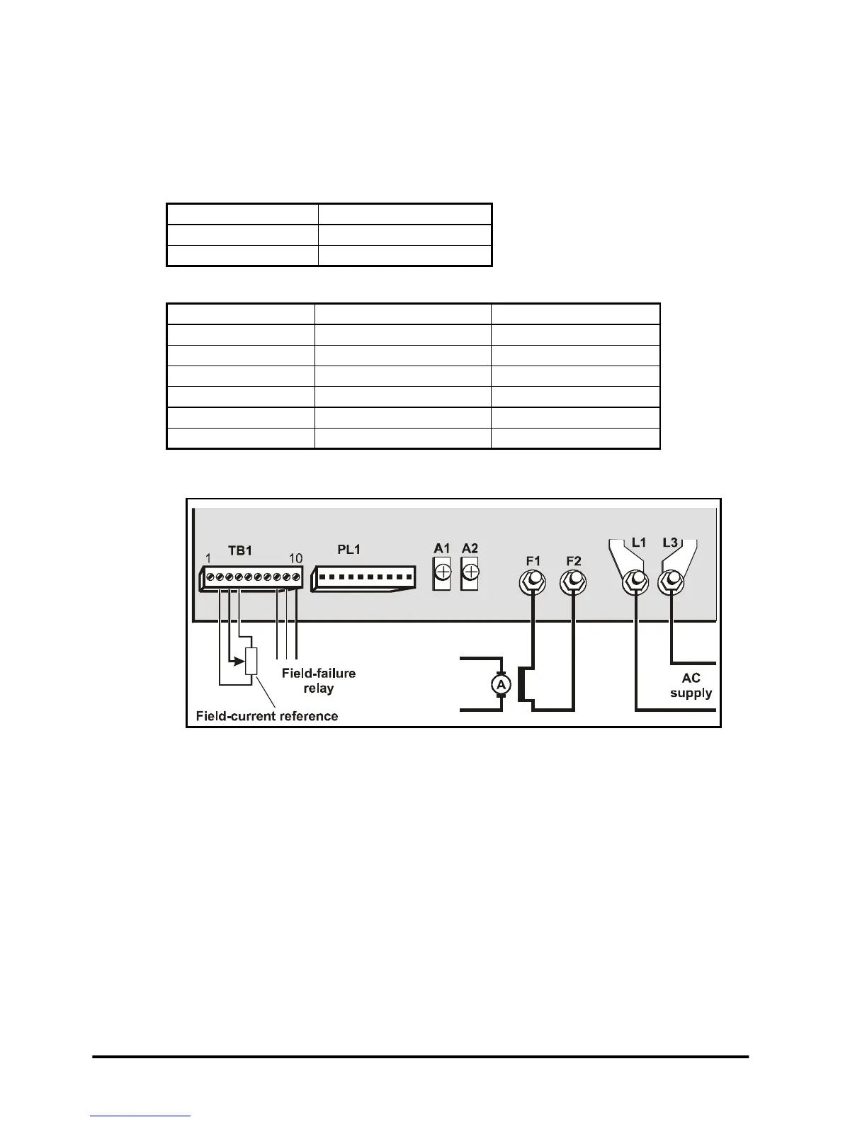
3.9.4 External control of the field current (variable or fixed levels)
Figure 3-8 Power and signal connections for external control of the field current
Model Jumper
M25toM210 LK1andLK2
M350 to M1850 LK1
Model Mentor Power Board Connector Designation
M25-M75 MDA75 PL6
M25R-M75R MDA75R PL6
M105-M210 MDA210 PL6
M105R-M210R MDA210R PL6
M350-M1850 MDA6 PL16
M350R-M1850R MDA6 PL16