FXM5 User Guide 13
Issue Number: 5 www.controltechniques.com
Make signal connections to terminal block TB1, as follows:
The field current must not be allowed to become zero while the motor is running.
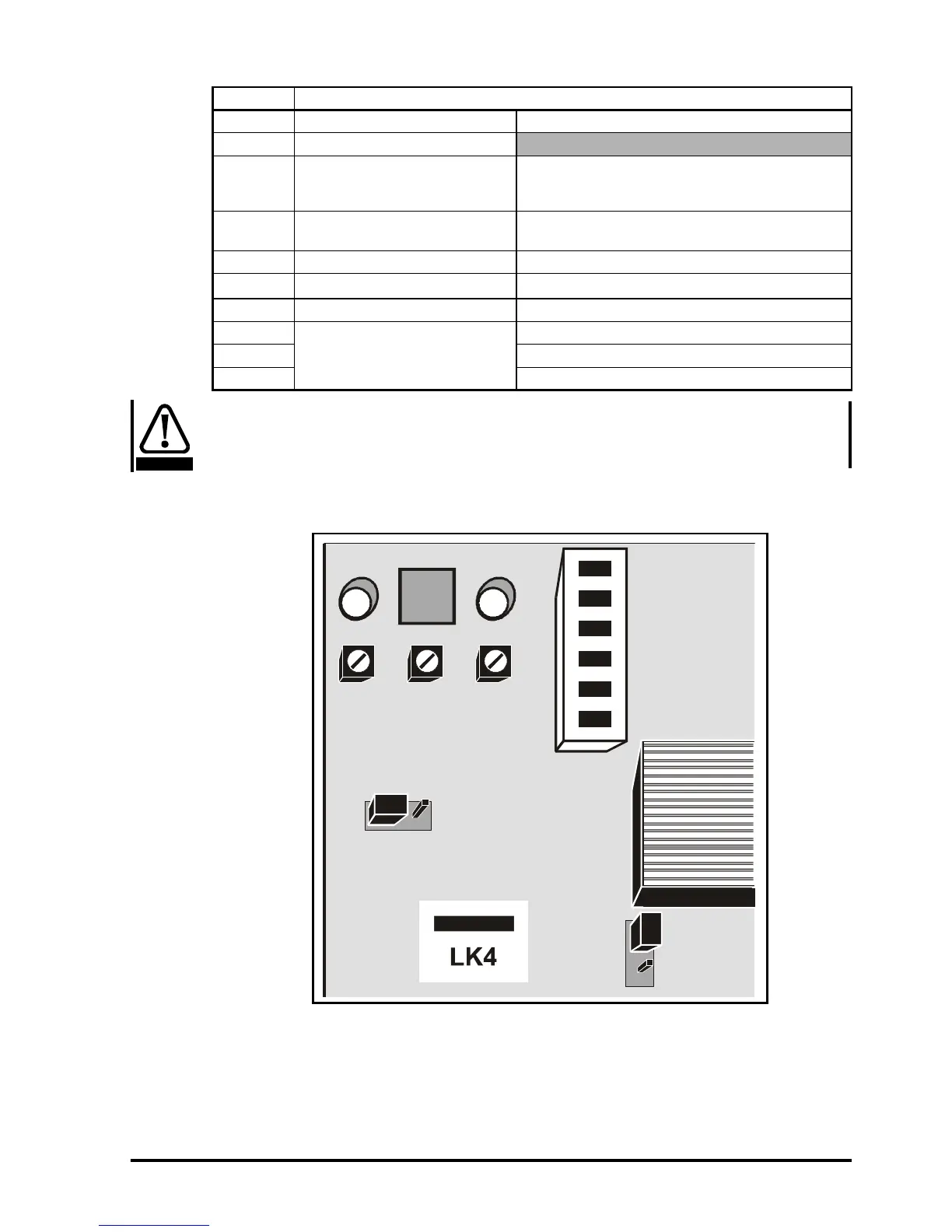
Cut the wire jumper LK4 since stages N1, N2 and N3 are not used and must not affect
the system (see section 4.2 Control-circuit description on page 16).
Figure 3-9 Location of wire jumper LK4
TB1 Function
1 Field economy contact Not used
20Vcommon
3
Field-current amplifier input
Apply an external field-current reference signal (0
to -10V)
Remove jumper LK4
4
-15V, 10mA max. output
Use to supply external devices
(e.g. external field-current reference potentiometer)
5 +15V, 10mA max. output Use to supply external devices
6
Field-current output signal
0-10V represents 0 to I
F
max
7 Armature-voltage output signal Not used
8
Field-current failure relay
Common contact
9 Contact closed when field current is normal
10 Contact open when field current is normal
CAUTION