Safety
Information
Product
Information
Mechanical
Installation
Electrical
Installation
Getting
Started
Menu 0
Running
the motor
Optimisation Macros
Advanced
Parameters
Technical
Data
Diagnostics
UL Listing
Information
42 Unidrive User Guide
www.controltechniques.com Issue Number: 9
Table 4-2 Maximum motor cable lengths (200V drives)
Table 4-3 Maximum motor cable lengths (400V drives)
• Cable lengths in excess of the specified values may be used only
when special techniques are adopted; refer to the supplier of the
drive.
• The default switching frequency for all versions of Unidrive is 3kHz,
except Unidrive LFT, which is 9kHz.
The maximum cable length is reduced from that shown in the table
under the following conditions:
• PWM switching frequency exceeding 3kHz in model sizes 3 and
4
The maximum cable length is reduced in proportion to the increase
in PWM switching frequency, e.g. at 9kHz, the maximum length is
1
/
3
of that shown.
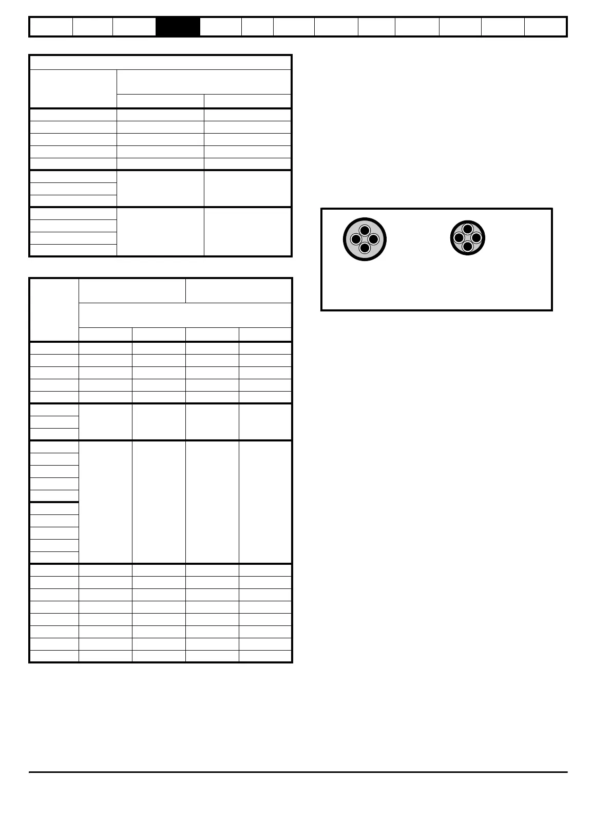
• High-capacitance cables
Most cables have an insulating jacket between the cores and the
armour or shield; these cables have a low capacitance and are
recommended. Cables that do not have an insulating jacket tend to
have high capacitance; if a cable of this type is used, the maximum
cable length is half that quoted in the table. (Figure 4-4 shows how
to identify the two types.)
Figure 4-4 Cable construction influencing the capacitance
The capacitance measured above is from one line to all others and is
obtainable from the cable manufacturer. This means the capacitance
from one core to all the other cores and the screen shorted together.
4.5.2 Multiple motors
Open-loop only
If the drive is to control more than one motor, make connections as
shown in Figure 4-5 and Figure 4-6. The maximum cable lengths given
in Table 4-2 and Table 4-3 apply to the total length of cable from the drive
to the farthest motor.
It is recommended that each motor is connected through a protection
relay since the drive cannot protect each motor individually. For star
connection, a sinusoidal filter or an output inductor must be connected
as shown in Figure 4-5 and Figure 4-6, even when the cable lengths are
less than the maximum permissible. For details, of inductor sizes refer to
the supplier of the drive.
200V Nominal AC supply voltage
Model
Maximum permissible motor cable length
(PWM switching frequency of 3kHz)
mft
UNI1201 65 210
UNI1202 100 330
UNI1203 130 430
UNI1204 200 660
UNI1205 300 990
UNI2201
300 990UNI2202
UNI2203
UNI3201
200 660
UNI3202
UNI3203
UNI3204
Model
400V Nominal AC supply
voltage
480V Nominal AC supply
voltage
Maximum permissible motor cable length
(PWM switching frequency of 3kHz)
mftmft
UNI1401 65 210 50 160
UNI1402 100 330 75 250
UNI1403 130 430 100 330
UNI1404 200 660 150 490
UNI1405 300 990 250 820
UNI2401
300 990 300 990UNI2402
UNI2403
UNI3401
200 660 124 410
UNI3402
UNI3403
UNI3404
UNI3405
UNI4401
UNI4402
UNI4403
UNI4404
UNI4405
UNI5401 300 990 300 990
UNI5402 600 1980 600 1980
UNI5403 900 2970 900 2970
UNI5404 1200 3960 1200 3960
UNI5405 1500 4950 1500 4950
UNI5406 1800 5940 1800 5940
UNI5407 2100 6930 2100 6930
UNI5408 2400 7920 2400 7920
Normal capacitance
Shield or armour
separated from the cores
High capacitance
Shield or armour close
to the cores