Coolerado Installation
Page 15 of 63
CAUTION: Failure to install an in-line water filter will void
system warranty.
NOTE: In addition to water pressure, water quality has a
major impact on performance. Reducing undissolved
particulates increases performance and longevity of the
system’s heat exchangers.
The filter will need to be changed when the pressure drop
across the filter reduces the main line water pressure below
25 psi at the units when they are calling for water, the toilets
are being flushed and the irrigation system is running.
Realistically the water pressure needs to be at least 40 psi.
How fast a water filter needs to be replaced depends on the
amount of un-dissolved minerals or debris that is in the
water.
NOTE: If incoming water pressure is more than 80 psig (550
kPa), a pressure-reducing valve should be installed to the
incoming water supply line.
WATER PRESSURE REQUIREMENTS
NOTE: If incoming water pressure is ever less than 25 psig
(172 kPa) when the unit is running, a water pressure booster
pump may be required. District water line pressures are
often decreased due to irrigation activities, especially at
night. A minimum building pressure is generally 40 psi to
maintain the pressure at the unit of 25 psi when considering
water filter pressure drop, perhaps a water softener, toilets
being flushed, the units may be mounted on the roof
causing pressure loss due to gravity and height, and the
irrigation system running.
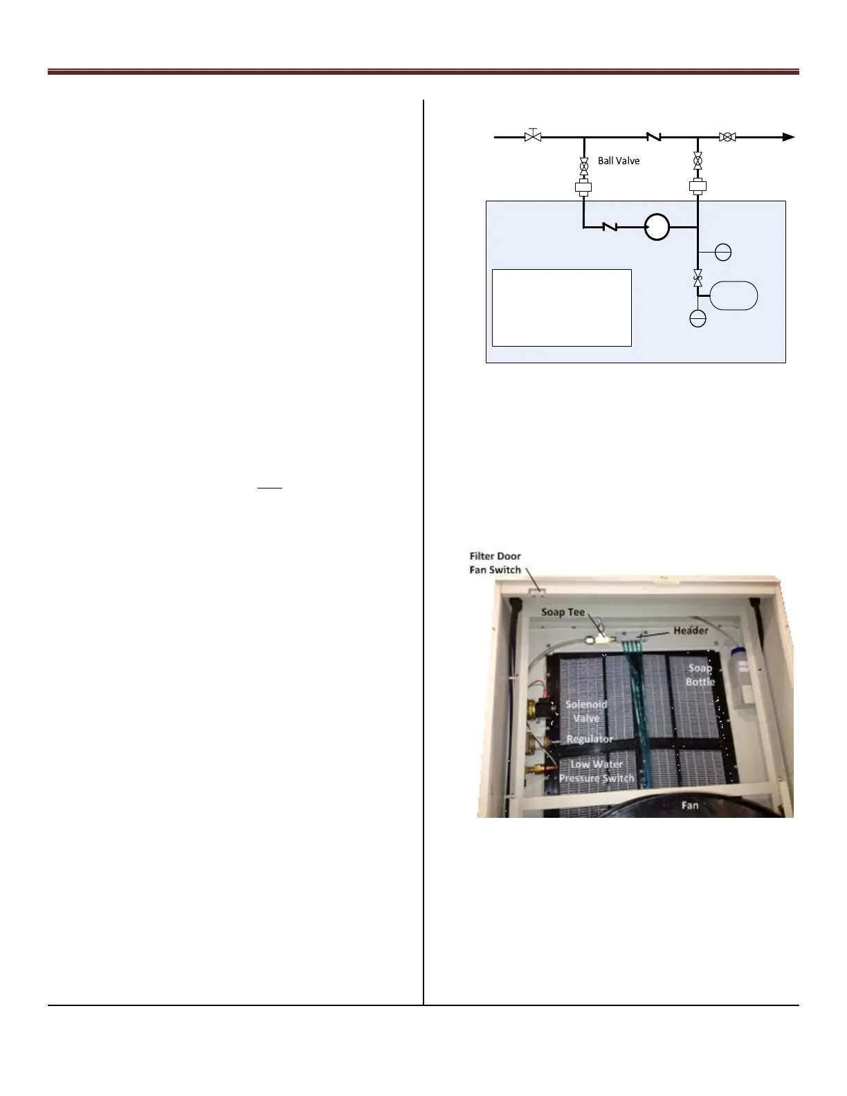
Low Water Pressure:
In certain locations, a reduction or potential loss of water
pressure can occur due to high demand conditions on the
municipal or district water supply. Install a booster pump to
ensure water pressure is maintained. If required, mount
booster equipment near ground level, see Figure 25.
Check Valve, CV
Booster
Pump
Pressure
Tank
Pressure
Gauge
Union
Relief Valve
Pressure
Sensor
Circuit Breaker
Disconnect (110VAC, 20 amp)
Control for Booster Pump
Need 25 psi (172 kPa)
Minimum at Coolerado Unit
By Contractor:
CV
Main Water Line
Hose Bib
Ball Valve
Water Booster, Hose Bib, and Ball Valve, Figure 25.
NOTE: Use a minimum of 1/2” (12.7 mm) diameter supply
water line, which should be free draining for winter shut
down.
BACK FLOW PREVENTION
NOTE: The unit is equipped with a self-draining water
regulating valve designed with a vacuum break in the HMX.
Water Distribution System – M50C, Figure 26
Freeze protection can be done manually:
1.) Install supply water shut off valve between the
water supply line and the unit.
2.) Install a drainage valve downstream of the manual
water valve. The drain valve should be located within
a conditioned space.