Coolerado Installation
Page 19 of 63
Power on: Green LED light
Water solenoid is powered: Clear light
Cool call: Yellow light
Flush cycle is on: Red light
Winter /summer: White light
The water control board has a fan speed potentiometer, (see
appendix 2). This is a single turn pot that controls the
maximum voltage going to the fan. If dip switch 7 is in the off
position the fan voltage can be turned between 0 and 10
VDC. If dip switch 7 is on, then this pot will proportionally
vary the voltage received at the water control board allowing
a maximum fan speed to be set. The factor setting is full
speed.
Note: If a three-speed fan is used the fan speed
potentiometer mentioned directly above may need to be
used to reduce fan speed, see appendix 10.
The water control board also has three switches mounted on
it for ease of maintenance, (see appendix 2):
1. WINTER switch allows the fan to be operated
through the cool call and AV fan but with the water
off. Putting in winter mode will also cause it to go
into freeze protection. The terminal connection
precedence over the board winter switch.
2. WETOUT momentary switch allows a maintenance
person to start a wet out cycle as long as there is a
Cool Call. A jumper across the Y and RC terminals
will cause a Cool Call.
3. PRIME momentary switch allows a maintenance
person to prime the soap pump by pushing it and
holding it till primed.
Step 13 – Thermostat
Note: Do not start unit till Step 15.
A standard thermostat can be used however most
thermostats do not have 0 to 10 VDC capabilities to drive the
Coolerado fully auto variable fan. For this reason, Coolerado
sells a variable speed thermostat.
NOTE: The efficiency of the Coolerado goes up significantly
as the speed is reduced, (4x at half speed), so variable speed
control is encouraged when possible.
NOTE: The thermostat should be mounted on an interior
building wall, free of drafts, and in an area unaffected by
heat producing machinery or appliances.
See Appendix 5, Thermostat Operation. For additional
information on the thermostat see Appendix 2, Control
Board and Wiring Diagram; Appendix 4, Coolerado
Thermostat Wiring; Appendix 5, Multiple Unit Control
Wiring and Appendix 6, Thermostat operation.
Step 14 – HMX Wet Out Logic
Note: Do not start unit till Step 15.
The unit is equipped with an automatic wetting system that
provides a significant boost to the heat and mass exchangers
wetting operations when the unit is powered up at initial
installation, for seasonal restart, or any other time that the
heat exchangers have dried out after the power has been
shut off.
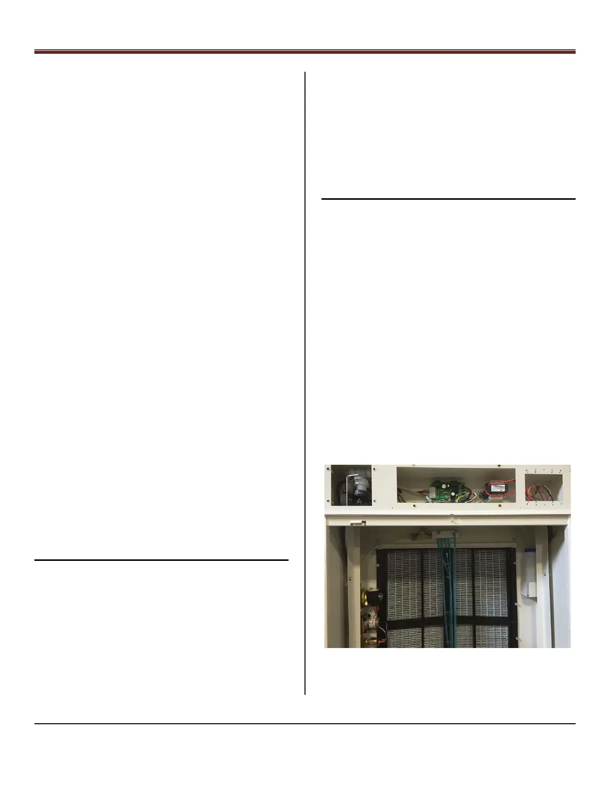
Water and Soap System, Figure 31
Soap Pump
Water Control Board
Transformer
Solenoid Valve,
Pressure Regulator
and Pressure Switch
Soap
Bottle