Coolerado Installation
Page 16 of 63
3.) Slope the line from the unit to the drain valve for
proper draining and freeze protection.
4.) To drain the line and water distribution system it
must be turned on for a few minutes to allow the
water to drain and air to pulled into the system. This
is done by turning the thermostat to require a cool
call.
WATER DISTRIBUTION SYSTEM
The water distribution system, (located inside the unit) is a
combination pressure regulator, 24 VAC solenoid valve and
water distributions manifold. The valve is designed to
deliverer the correct water flow to each of the systems heat
exchangers.
NOTE: Water Distribution System pressure should be
adjusted in the field to 5.5 psi, (38 kPa). The adjustment
must be made in the field to adjust for elevation above sea
level.
CAUTION: It is absolutely essential that the pressure
regulator be set to deliver the proper pressure at the water
distribution head before installation can be considered
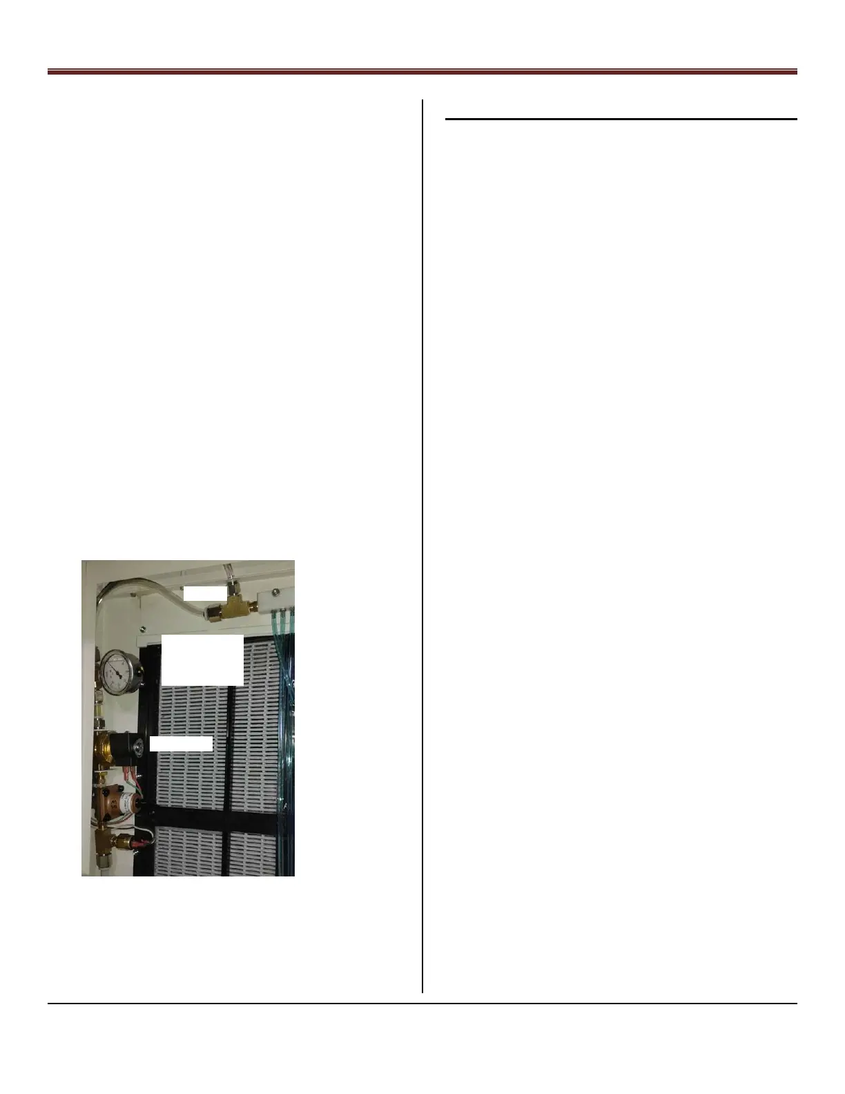
complete. For the most accurate setting possible, take a
dynamic pressure reading at the point where the water
supply enters the water distribution head. This can be done
by temporarily installing a pressure gage immediately at the
point where the water supply enters the water distribution
header, as in the following picture, and adjusting the
dynamic pressure to the desired level.
Water Header Pressure Location, Figure 27.
Step 10 –Electrical Power Connections
Note: Do not power on the unit until Step 15.
See Appendix 2 for Details.
See Appendix 4 for multi-unit wiring.
DANGER: To avoid personal injury or death, do not supply
power to unit with the units’ high voltage terminal box
cover removed.
WARNING: NOT SUITABLE FOR USE WITH SOLID-STATE
SPEED CONTROLS
CAUTION: Be sure field wiring complies with all local and
national fire, safety, and electrical codes, and voltage to
system is within limits shown on unit rating plate. Contact
local power company for correction of improper voltage.
See unit rating plate for recommended circuit protection
device.
NOTE: Keep wiring color coded according to system
drawings for easy troubleshooting and standardization. For
color code reference, see Appendix 2.
NOTE: Operation of the unit on improper line voltage
constitutes abuse and could affect unit reliability. See the
unit rating plate. Do not install unit in system where voltage
may fluctuate outside of normal voltage fluctuations
NOTE: Use copper conductors only between the disconnect
switch and the unit.
ROUTE GROUND AND POWER WIRES
DANGER: The unit cabinet must have an uninterrupted or
unbroken ground to minimize personal injury if an electrical
fault should occur. The ground may consist of electrical wire
or metal conduit when installed in accordance with existing
electrical codes. Failure to follow this warning can result in
an electric shock, fire, or death.
CAUTION: Without an uninterrupted or unbroken ground
the motor can have arcing across the bearings causing
premature failure of fan motor.
Remove access panel and electrical box cover to gain access
to unit wiring. Extend wires from disconnect through power
wiring hole provided and into unit control box. Size wires per
National Electric Code.
CONNECT GROUND AND POWER WIRES
Single Phase Motors: The unit fan motors will run on 200 to
277 VAC, 50/60 Hz single phase with an electrical circuit
breaker of 5 amperes. The transformers provided are 208
VAC or 240 VAC to 24 VAC only. In some instances, a 277 VAC
Measure Header
Pressure Between
Solenoid Valve and
Soap Tee Using ½”
OD Tube Connectors
Solenoid Valve
Soap Tee