Coolerado Installation
Page 8 of 63
Outdoor Air
Inlet
Supply Air
Exhaust Air
Note, Opening cut into Supply
Plenum by Contractor
Outdoor Air
Inlet
Contractor
Fabricated
Exhaust Duct
Supply Air
Exhaust Air
Clearances:
-- Sides: 0
-- Top: as needed for installation
-- Outside Air Intake to Fan: 24" (600 mm)
-- Supply Air Plenum: as needed for
installation
Clearance Requirements, Figure 7
Step 4— Install on a Solid and Level Foundation
Mount the unit on a solid and level foundation with
proper sub-base and drainage to ensure the unit will
not shift during its lifetime.
Take the proper precautions when mounting the
unit to reduce noise and vibration.
If mounted on rafters, use appropriately sized
vibration damping springs and duct isolation
attachments.
If installed on a roof, an attic, or any place where
structural support may be an issue, consult with a
structural engineer and comply with local code
requirements.
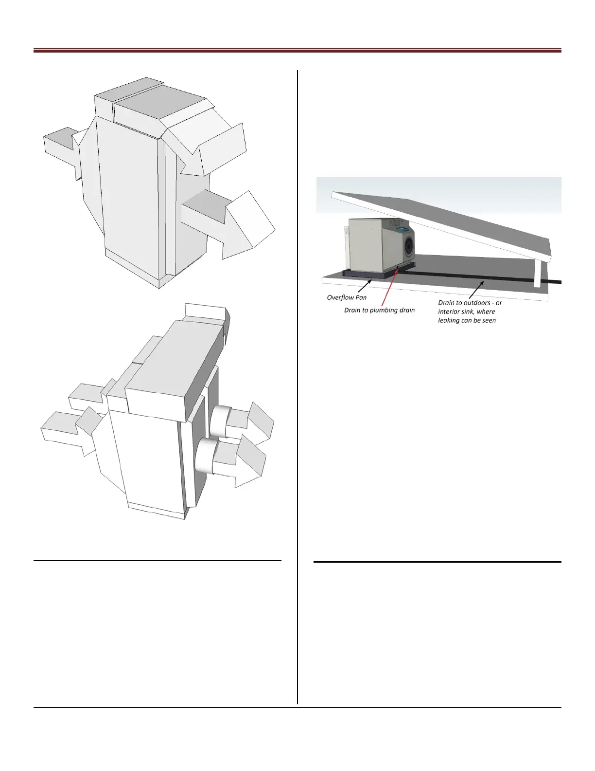
If unit is installed indoors, install an emergency drain pan that
extends beyond the unit by at least 6” (150 mm) on all sides
along with separate overflow drain directed to a sink or
outside location where the leak can be seen and in
accordance with local plumbing codes, see Figure 9.
Overflow/Drain Example, Figure 9
LEVEL UNIT
The weight of the wet unit will require a stable base. During
installation, the unit must be properly supported and leveled
to stay stable over time. The water delivery to all areas inside
the unit depends on the unit being level within 1/16” per foot
(5.2 mm/meter) in both directions. CAUTION: Failure to do
so will void system warranty.
CAUTION: Foundation racks or solid drainage
footing/concrete pads must be used on ground installations
to ensure the unit remains level and secure. Proper
preparation of ground is necessary to maintain level footing
over time.
CAUTION: Do not place unit directly underneath roof, eaves
or drip lines without adequate gutters.
Step 5 – Drain Connections
NOTE: The units drain connection is located underneath the
unit’s intake air plenum.
Install system drain piping that can be 1 ½” (38.1 mm) pipe
over outside; 1 ¼” (31.75 mm) inside or 40mm deeper inside
If local or state codes allow drain water to be used for
Irrigation, it must be drained away from the pad to eliminate
any settling that will prevent the unit from remaining level. If
this occurs, the drain line must slope a minimum of 1/8” per
foot (10.4 mm/meter).