Coolerado Installation
Page 17 of 63
is required and the transformer can be requested at time of
purchase.
15 amperes is generally the smallest circuit breaker that can
be purchased. Local electrical codes shall be applied and take
precedence over any recommendations given here.
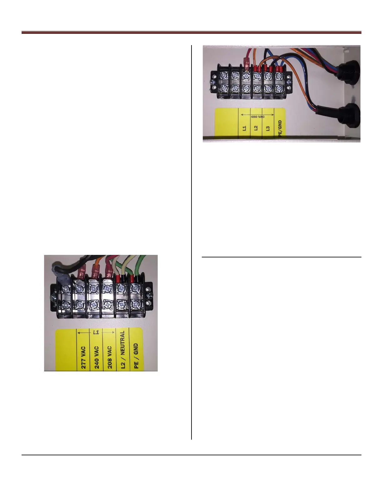
The M50 has a terminal electrical box at the bottom of the
unit, see Appendix 10. Notice the Black Jumper wire with the
spade connection must be moved from the blank terminal to
the 208, 240 or 277 VAC terminals see Figure 28.
1~ Electrical Power Connections, Figure 28
Three Phase Motors; 480 VAC, 50/60 Hz with an electrical
circuit breaker of 10 amperes each leg.
3~ Electrical Power Connections, Figure 29
CAUTION: The transformer was not designed to power other
equipment.
NOTE: The electrical access panels have screw holes to fit
most electrical box covers making it easy to install switches,
outlets, etc.
CAUTION: Line Voltage and Control wires must be routed
clear of any system components such as filter access doors
to prevent wiring chafing / electrical shorts.
CAUTION: Ensure line and control voltage wires are routed
away from terminal connections and control board.
Step 11 – Control Wiring
Note: Do not start unit till Step 15. See Appendix 2 for wiring
instructions.
CONTROL REQUIREMENTS
Input Cool Call “Y” (1
st
stage cooling call)
Variable Speed Fan, 0-10 VDC signal or no signal and
full speed; dipswitch 7 OFF
Winter/Summer mode; if fan to be used in winter
Freeze Protection relay; if needed
NOTE: The water control board provides 24 VAC (via
terminal RC) to be switched thru a dry contact back to
terminal Y.
Eight Pin plug in Cable Connector on water control
board and wired to a wire terminal block
1. Y – Cool Call dry contact
2. RC - 24 VAC
3. Variable Speed Fan controlled by 0-10 vdc
4. Common