16
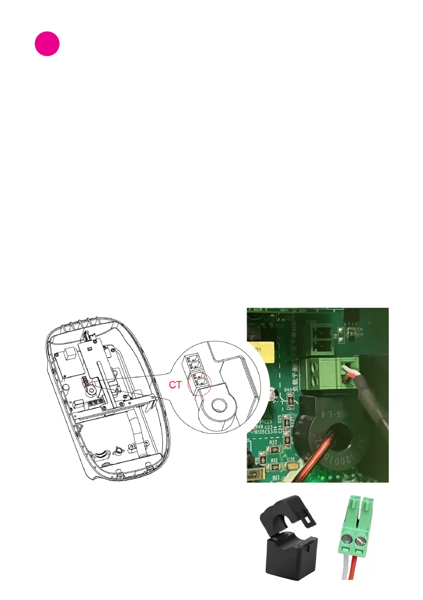
Step 1: CT clamp connection
• Turn off the charger for CT clamp connection.
• ConnecttheCTconnectortotheCTportofthechargepointasshowninthegure.
• Clamp the CT to the same phase of the consumer unit where the charger is.
connected. Make sure this step is done only after the CT connector is connected to.
chargepointtopreventelectricalhazards.
• Ensure that the CT clamp is connected tightly with the correct polarity. Please
check the image below.
CT Clamp
7.1 Load balance conguration
Thiscongurationappliesforasinglechargepointwithresidentialload.
Thisbalancesenergyuseandadjuststhechargingoutputtoyourelectriccarinresponse
to changes in electricity load.
CT port for load balance
Installation Tests and
Congurations
7