Standard Recommended Procedure 003-794-AEN | Issue 14 | March 2020 | Page 21 of 27
Step 1: Frame/Cabinet Location (Figure 26)
Identify location of Frame or Cabinet within the oor space grid coordinate system. Preprint labels
and adhere to Front and Back of Frame or Cabinet at the top and bottom.
Figure 26 — Frame/Cabinet Label Location
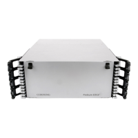
Step 2: Housing/Chassis Location (Figure 27)
Identify location within the Frame or Cabinet (in rack units from the bottom) by locating the Top/Left
corner of the housing/chassis. Print two labels and adhere one to the front chassis door using the crop
mark for alignment. Adhere the second label to the label card on the inside of the door.
Figure 27 —Housing/Chassis Label Location