MA 1000M Installation and Configuration Guide
1
1
I
I
n
n
t
t
r
r
o
o
d
d
u
u
c
c
t
t
i
i
o
o
n
n
t
t
o
o
M
M
A
A
1
1
0
0
0
0
0
0
S
S
y
y
s
s
t
t
e
e
m
m
1.1 About MA1000
The MA1000 provides enterprise level indoor coverage for a wide range of wireless services over
a single broadband infrastructure.
The MA1000 is a single operator, multi-band system based on combining a number of services,
voice and data, and distributing them to each remote location through a common antenna
infrastructure. These include Cellular, Paging, Public Safety and LTE SISO signals.
Cellular services are bi-directionally transferred between the capacity source (BTS/BDA) and the
remote locations using low loss fiber and broadband coax.
WLAN services from Wi-Fi Access Points (802.11 a/b/g/n) can be integrated with the MA1000
system at the remote sites for transport over a single cabling infrastructure to the antenna.
1.1.1 Features
• A multi-service platform that accommodates the combination of cellular and enterprise
services (e.g. WLAN, WMTS Telemetry and 900MHz Building Automation), eliminating the
need for separate overlay networks
• Carrier Class QoS – advanced signal handling and management ensures optimal performance
for all services
• Local and remote end-to-end monitoring and control through an interface to 410, 430 or SC-
450 system controller
• Low power system requirements eliminates the need for a high power capacity source’s,
reducing operator expenses
• Comprehensive conditioning and monitoring of RF signals at the head-end through an
interface to the Radio Interface Unit (RIU)
• Reduce cost through the support of multimode fiber
• Software programmable parameters including output power, AGC (on/off and levels), and
system gain
• Real time component setting capabilities for optimal performance
1.2 System Architecture
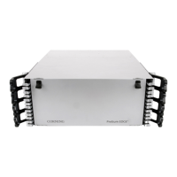
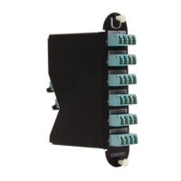
The MA1000 solution is based on the following main elements:
• Base Units (BUs) – The BUs perform RF to optic conversion on the BTS side.
• MA Remote Hub Units (RHUs) 1000 – The MA 1000 performs the RF to optic signal
conversion at the antenna side for up to two services corresponding to the RHU model. A
third service can be added by connecting an add-on remote hub unit to the MA1000 RHU.
• Add On – Service specific module that provides support for an additional service to an
existing RHU.
• 700 LTE SISO add-on – Add-on module specifically designed to support LTE SISO in the
700 MHz lower A, B and C blocks and the upper C block. (The LTE add-on model varies
depending on whether or not it is used in conjunction with the 700/800 Public Safety RHU).