Appendix A: System Specifications
MA1000 Installation and Configuration Guide 29
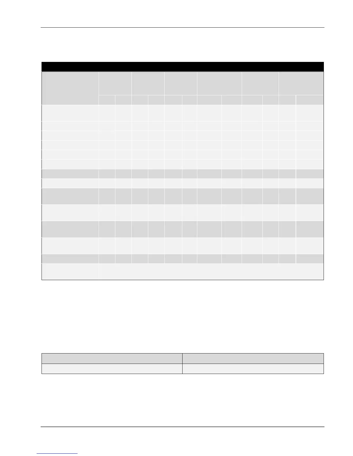
High Band Services
MA1000 RHU RF Parameters - High Band Services
MA1000 RHU
RF Parameter
DCS
PCS
5
CDMA /
WCDMA
PCS
5
GSM /
TDMA
G-PCS
6
CDMA/WCDMA
G-PCS
6
GSM/TDMA
UMTS and
AWS
CDMA/WCDMA
DL UL DL UL DL UL DL UL DL UL DL UL
Max Output Power
/ Antenna Port
1 (Composite) 16
20
20
20 21 21
2 Carriers 13
17
17
17 18 18
4 Carriers 10
14
14
14 15 15
8 Carriers 7
11
11
11 12 12
12 Carriers 5
9
9
9 10 10
Mean Gain(dB)
1
16 3 20 3 20 3 20 20 3 21 3
Pin (dBm)
1
0
0
0
0 1 0
Input IP3 (dBm)
AGC OFF Min
-6
-6
-6 -7 -7 -7
Input IP3 (dBm)
AGC ON Min
3
3
3
SFDR
2
(dB)
65
67
70/
65
66 64 66
Max Intermod
Distortion (dBm)
-30
-
13*
-13
-13* -13 *
Max NF (dB)
18
18
18
Gain Flatness /
Ripple (dB)
3
+/-2.0
* WCDMA compiles with 3GPP TS 25.106 V5.0.0 (2002-03) table 9.4 spectrum emission mask.
1
Factory set mean gain BU-RHU without RIU. May be field adjusted using controller system.
2
SFDR for CDMA services is calculated in 100KB/sec.
3
Gain Flatness/Ripple is specified for the non-duplexed port of the system.
5The PCS service RF specifications outlined is relevant only for the MA1000 CELL/PCS RHU, CELL/PCS/700LTE TSX, CELL/PCS/AWS TSX
and CELL/PCS/700LTE/AWS QSX
6
The PCS service RF specifications outlined is relevant only for the MA1000 PCS AO and IDEN/SMR/PCS TSX
Absolute Maximum Rating
Total Input RF Power to BU 10dBm
Power Supply 60VDC