Preface Material
MA1000 Installation and Configuration Guide 10
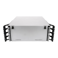
2.2.1.1 BU Front Panel
The front panel contains the optical connections and indicators. The BU is available in two
configurations: Four-port - and Eight-port BUs. The eight-port BU consists of two four-port
elements where each four-port element has a dedicated set of indicators (PWR, LSR and Link 1
to Link 4 or Link 5 to Link 8).
Figure 9. Eight-Port BU Front Panel
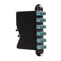
Figure 10. Four-Port BU Front Panel
Table 2-5. BU Front Panel Indicators
LED Description
PWR Power input detected for the corresponding unit.
LSR
ON - laser circuitry for the corresponding element (group of four ports) is
functioning correctly.
Link 1-4, 5-8
ON - the optical link to/from the connected remote functions within the
specifications in both directions.
Blinking - optical power from remote is lower than expected by at least 2 dBm
Four ports and corresponding indicators
Four ports and corresponding indicators