Preface Material
MA1000 Installation and Configuration Guide 11
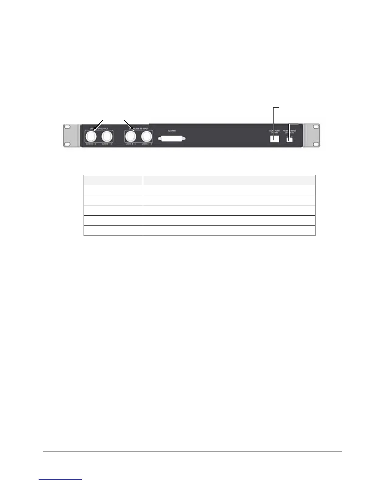
2.2.1.2 BU Rear Panel
The BU rear panel contains the RF, NMS, and power connections. Note that there are two uplink
and two downlink RF connections to the BTS side (to an Interface Box or RIU) - each individual
uplink and downlink connection corresponds to a four-port BU element. For a four-port BU, one
uplink and one downlink port is connected; for an eight-port BU, two uplink and two downlink
ports are connected.
Figure 11. BU Rear Panel (RF Connections)
Table 2-6. BU Rear Panel Connections
Connector Description
Uplink output Uplink connectors to be connected on BTS side.
Downlink input Downlink connectors to be connected on the BTS side.
Com Port RS485 Connection to 410, 430, SC-450 controller.
PWR Power connection
Alarms N/A
Pair of uplink and downlink RF
connections for interface to BTS
To 410/430/SC-450
controller
Power