Appendix A: System Specifications
MA1000 Installation and Configuration Guide 28
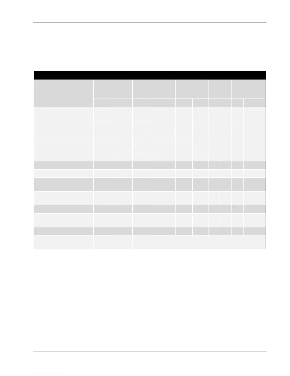
RF Parameters per Service
Low Band Services
MA1000 RF Parameters - Low Band Services
RF Parameter
LTE 700 MHz
CELL TDMA /
CDMA / WCDMA /
GSM800
SMR 800
6
GSM /
E-GSM
SMR 900
6
DL UL DL UL DL UL DL UL DL UL
Max Output Power /
Antenna Port
1 (Composite) 21 20
20
14
20
2 Carriers 18 17
17
11
17
4 Carriers 15 14
14
8
14
8 Carriers 11
11
5
11
12 Carriers 9
9
3
9
Mean Gain(dB)
1
21 20 7 20 7 14 7 20 7
Pin (dBm)
1
0 0
0
0
0
Input IP3 (dBm) AGC OFF
Min
-10
-5
-5
-5
-5
Input IP3 (dBm) AGC ON
Min
5
5
5
5
SFDR
2
(dB) 55
68/69/73
72
68
74
Max Intermod Distortion
(dBm)
** -13*
-13
-
36
-
13
Max NF (dB) 20
20
20
16
16
Gain Flatness / Ripple
(dB)
3
+/-1.0
5
+/-1.5
* WCDMA compiles with 3GPP TS 25.106 V5.0.0 (2002-03) table 9.4 spectrum emission mask.
**Out of band and spurious emissions compliant with FCC standards.
1 Factory set mean gain BU-RHU without RIU. May be field adjusted using controller system.
2 SFDR for CDMA services is calculated in 100KB/sec.
3 Gain Flatness/Ripple is specified for the non-duplexed port of the system.
4 Specifications include the 900 MHz UL filter. The output power is limited on the downlink.
5 Gain Flatness/Ripple at any block of the spectrum.
6 The SMR 800/900 for Sprint are to be designed, per Sprint guidelines, with composite power levels per antenna port and mean gain values 3dB
less than stated.