46 LIMIT SWITCH ADJUSTMENT INSTALLATION MANUAL
LIMIT SWITCH
ADJUSTMENT
ELECTRICAL WARNING:
Disconnect or turn off the power supply before
starting any work on the Covana cover.
Additionally, all electrical work should be
performed by a qualified electrician.
Note: The up and down limit switches have been
factory-adjusted and there should be no need to
re-adjust them. If adjustments are required to
ensure the Covana cover does not come in
contact with surrounding obstacles while being
raised, the maximum height may be reduced.
Never change the factory setting of the down limit
nor increase the up limit beyond the factory
setting. Failing to do so may result in equipment
damage and/or injury.
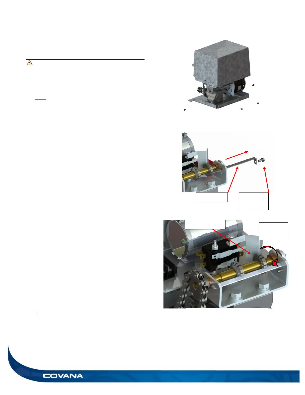
1) Disconnect or turn off the power and lock out the
power source.
2) Remove the four hex head screws at the bottom
of the operator and remove the cover. (Figure 86)
3) Remove the hex head retaining screw and slide
the cam plate out from operator frame. (Figure
86) (Be careful not to move the cam wheels.)
4) To reduce the amount of travel in the upward
direction, turn the up cam wheel counter
clockwise viewed from the cam plate retaining
screw end as shown. (Figure 88) When turning
counter-clockwise, for each cam wheels lot travel
(approx. 4°), the upper cover limit will be reduced
by approximately 5/32 in. (4 mm).
5) Once the height is set to the desired position,
reinstall the cam plate to its original position and
ensure that it is properly inserted in the slot of
each cam. Never operate the system without
the cam plate and retaining screw. (Figure 87)
6) Reinsert the hex head retaining screw to prevent
the cam plate from coming out.
7) Reinstall the operator cover.
8) Turn the power on and test the system.
9) Screw the cover back on using the 4 hex head
screws. (Figure 86)
Figure 87