22 INSTALLATION INSTALLATION MANUAL
Assembly
WARNING
Before assembling, keep in mind not to over
tighten bolts. Power tools must not be used. The
bolts will break under excessive torque.
Note: The following figures represent the
assembly of an 8’ model. Panel size may vary.
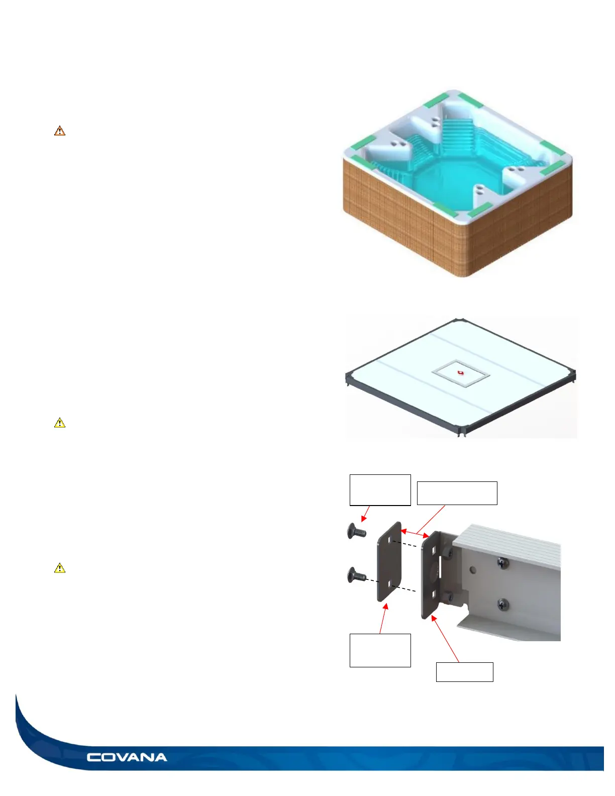
1) Attach the foam spacers to the top of the hot tube
near each corner using the masking tape
provided in the seal bag. There must be at least
3 foam spacers on each longest side. Do not
stack two pieces of foam high. (Figure 37)
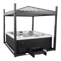
Note: The cover is rectangular. The standard
model will need the motor frame to be on the short
side of the Covana cover, whereas the long-side
will need the motor frame on the long side of the
Covana cover. Only the 8 feet model Is available
in the longside version. (Figure 38)
CAUTION
The foam pieces must be placed on the flat top
surface of the hot tube. (Figure 37)
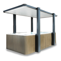
Two I-to-C-channels connections must be
installed per I-beam.
2) Use 1/4 in.-20 x 5/8 in. carriage bolts, 1/4 in.-20
nuts and 7/16 (11 mm) socket wrench and
spanner. (Figure 39)
CAUTION
Ensure these bolts and nuts are slightly
untightened, leave a 1/4 in. (6 mm) gap between
the I-to-C-bracket and plate.