51
INSTALLATION PROCEDURE
(1) Open the inverter wiring box.
(2) Bring the communication cables into the wiring box through the provided
knockout holes at the bottom.
(3) Connect the RS485 wires to the green Phoenix connector ensuring correct
polarity and using a shielded twisted pair cable.
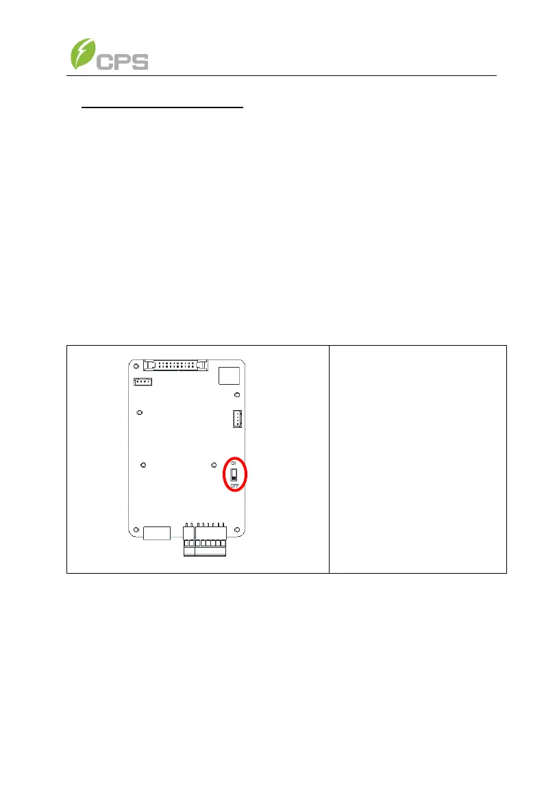
(4) If the inverter is the last Modbus device in the daisy chain, make sure the
Modbus termination switch S201 is in the ON position enabling Modbus
termination. Do not turn the switch to the ON position in any other inverters of
the daisy chain.
(5) Connect the shield or drain wire continuously, but not in contact with RS
(Common) or Enclosure Ground. Single-point ground the shield/drain wire.
(6) Do not connect RS485 Common to ground.
S201 - Selector switch for the
120Ω RS-485 termination
resistor
On - Enable the Modbus (RS-
485) bus termination (Applies
only for the last inverter in the
daisy chain)
Off - Disable the Modbus (RS-
485) bus termination. (Factory
default)
Figure 3-31 The Modbus (RS485) Termination Switch (S201) Location and
Settings on the LCD/Communication Board.