17. Attach the ON/OFF switch
assembly to the front RH leg of the
stand with (2) ¼-20 x 1-1/2” hex
bolts and (2) ¼” flat washers as in
(Fig.29).
Figure 29
18. Install the dust box underneath
the table as in (Fig.30) with the (4)
10-24 x 3/8 Phillips head screws.
Note: The vent should be facing
the front of the machine.
Figure 30
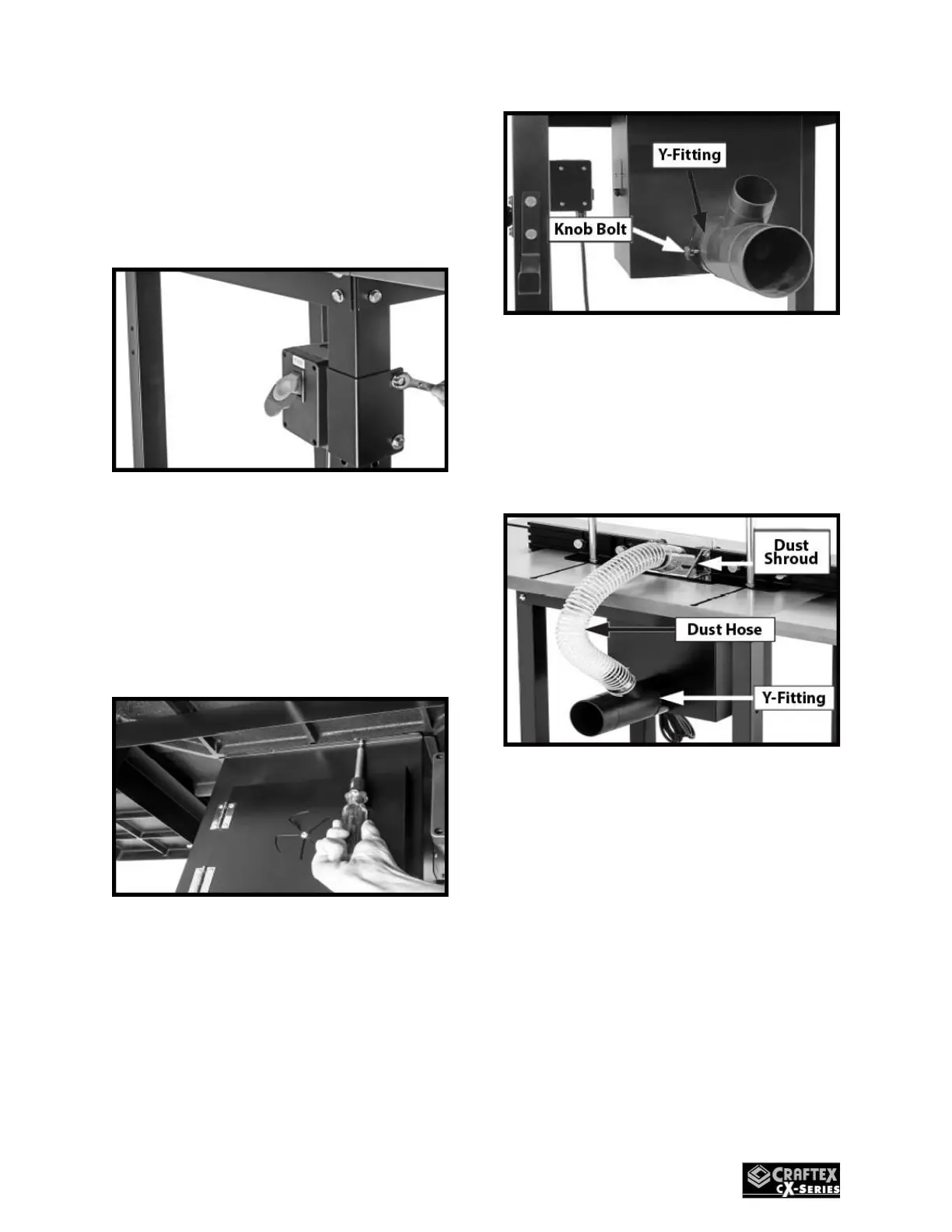
19. Install the Y-dust fitting as in
(Fig.31) over the dust port and
secure it with (1) ¼-20 knob bolt.
Figure 31
20. Attach the 2-1/2” dust hose on the
dust shroud and connect to the Y-
Dust Fitting. Secure with the 2-
1/2” hose clamps supplied. (See
Fig.32).
Figure 32
21. Install the fence storage brackets
and crank handle storage bracket
with (6) 5/16-18 x ½” flange bolts
as in (Fig.33).
 Loading...