4. Removethe idlerpulleybyremovingtheboltand nut.
SeeFigure27.
5. Removetheold beltandinstallthenewbelt.Followtheinstruc-
tionsin reverseorderto re-installthe beltkeeperandbelt cover.
SeeFigure27.
NOTE:Uponreassernbly,makecertainthebelt is routedoverthe idler
pulleyandinsideofthe beltkeepersbytheenginepulley.
TINES
Thetineswillwearwithuseandshouldbeinspectedat thebeginningof
eachtillingseasonandafterevery30operatinghours.Thetinescan be
replaced.Referto thePartsListsectionofthismanualforpartnumbers.
Tine Inspection
Withuse,thetineswill becomeshorter,narrowerandpointed.Badly
worntineswill resultina lossof tillingdepth,andreducedeffective-
nesswhenchoppingupandturningunderorganicmatter.
Removing/Installing a Tine Assembly
1. Removethetine shieldendcoversand sideshieldsbyremoving
thethree wingnutsoneach sidethatsecurethem.
2. Afine assemblyconsistsofa lefthandfineanda righthandfine.
NOTE:Thefineassemblymovesina counter-rotatingmotionwith
thesharpedgesof thetinespositionedtoenterthesoil firstwhen
counter-rotating.Notethis positionof thetinesfor reinstallationof the
newfine assemblies.
3. To removeafine assembly,simplyremovetheinternalcotterpin
securingtheclevispin. SeeFigure29.
• ® Clevis Pin
/
_ J
Figure29
4. Removetheclevispin andslidethe assemblytotheoutsideof
theunitandoff ofthe fineshaft.
5. Beforereinstallingthefineassembly,inspectthetine shaftfor
rust,roughspotsorburrs.Lightlyfileor sand,as needed.Applya
thincoatof greaseto theshaft.
6. Installeachfine assemblyso thatthe cutting(sharp)edgeof the
tineswillenterthesoilfirstwhenthetillermovesforward.Keepin
mindthatthesetinesarecounter-rotating,so securethetineas-
semblytothe tineshaftusingtheclevispinandinternalcotterpin.
ADJUSTMENTS
Handle
Thehandlemaybeadjustedto thedesiredheight.Refertothe
Assemblysectionfordetails.
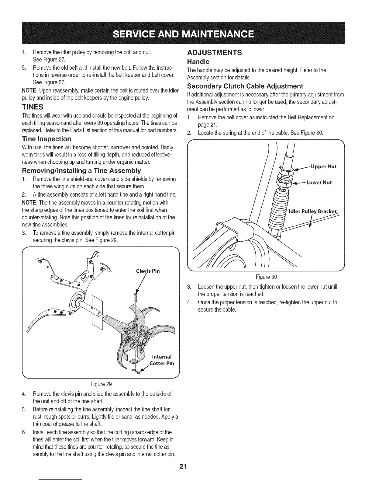
Secondary Clutch Cable Adjustment
Ifadditionaladjustmentisnecessaryafterthe primaryadjustmentfrom
theAssemblysectioncan nolongerbe used,thesecondaryadjust-
mentcanbeperformedasfollows:
1. RemovethebeltcoverasinstructedtheBelt Replacementon
page21.
2. Locatethespringat theendof thecable.SeeFigure30.
.
4.
Figure30
Loosentheuppernut,thentightenor loosenthe lowernut until
thepropertensionis reached.
Oncethepropertensionisreached,re-tightentheuppernutto
securethecable.
21