NOTE:Thisunitis shippedwithoutgasolineor oil intheengine.Be
certaintoserviceenginewithgasolineandoil asinstructedin the
Operationsectionofthis manualbeforeoperatingyourmachine.
NOTE:Referenceto rightand lefthandsideof thetiller isobserved
fromtheoperatingposition.
OPENING CARTON
1. Removethe staples,breaktheglueonthe topflaps,orcut the
tapeat theendof thecartonand peelit alongthetop flapto open.
2. Removeall looseparts.
3. Cutthe cornersandlaythe cartondownfiat.
4. Removeloosepackingmaterial.
REMOVING UNIT FROM CARTON
1. Usethe handlebartoliftand pullthetiller backwardstoa flat
area.Checkthecartonthoroughlyforlooseparts.
2. Extendthe controlcableandlay iton thefloor.Becarefulnotto
bendor kinkthecontrolcable.
LOOSE PARTS IN CARTON
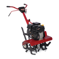
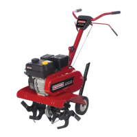
• HandlebarAssembly
• Tiller
• EngineOil
• Operator'sManual
• ShiftRod
• DepthStake
ATTACHING THE DEPTH STAKE
Beforeassembly,disconnectthe sparkplugwireandgroundit
againsttheengineto preventunintendedstarting.
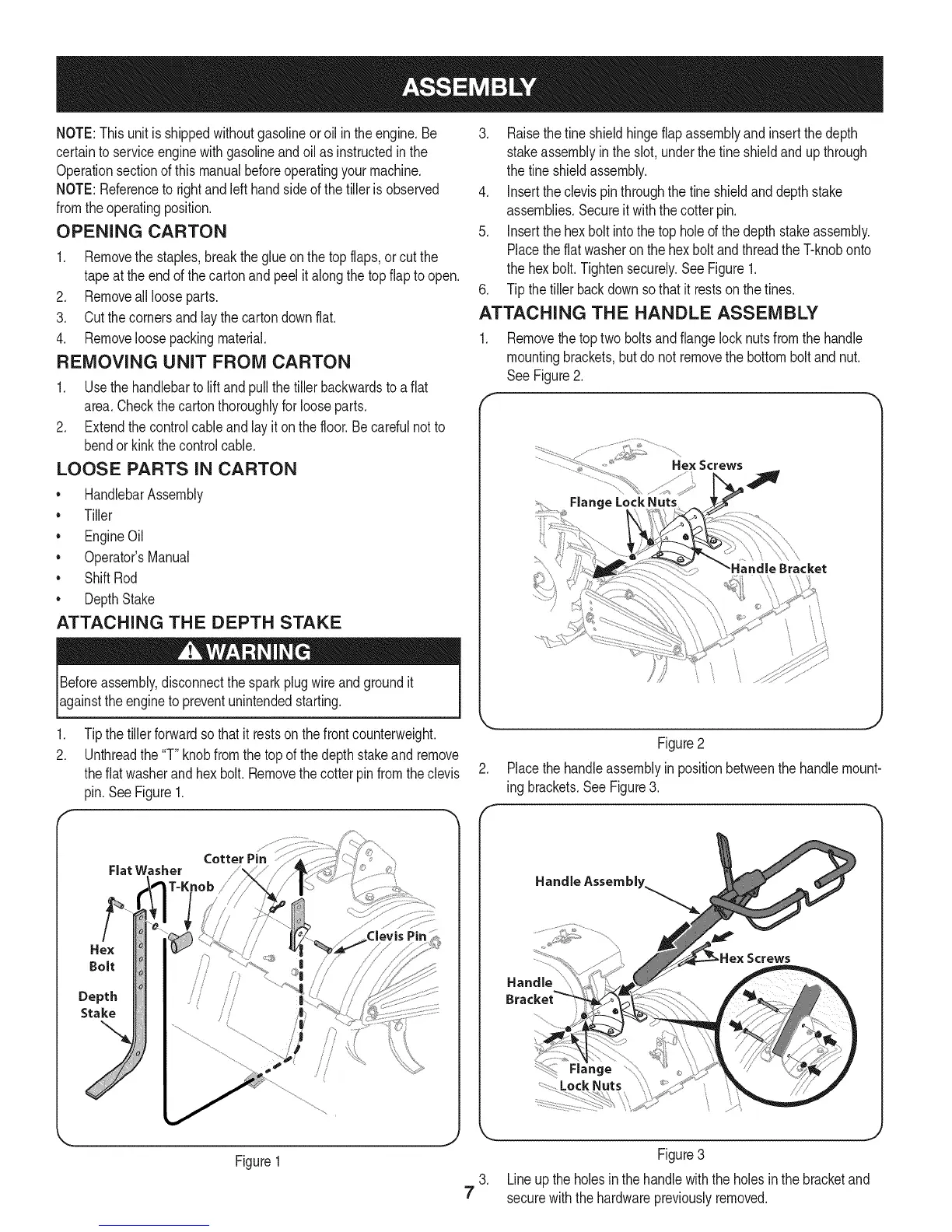
1. Tipthetiller forwardsothatit restson thefrontcounterweight.
2. Unthreadthe"T"knobfromthe topof thedepthstakeand remove
theflat washerand hexbolt. Removethecotter pinfromtheclevis
pin.SeeFigure1.
Cotter Pin
Fiat Washer
Hex
Bolt
Depth
Stake
Figure1
3. Raisethefine shieldhingeflapassemblyand insertthe depth
stakeassemblyinthe slot,underthe fineshieldandup through
thetine shieldassembly.
4. Inserttheclevispinthroughthe fineshieldanddepthstake
assemblies.Secureitwiththe cotterpin.
5. Insertthehex boltintothetop holeofthe depthstakeassembly.
Placetheflatwasheronthe hexboltandthreadthe T-knobonto
thehex bolt.Tightensecurely.SeeFigure1.
6. Tip thetiller backdownso thatit restsonthe tines.
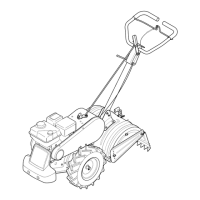
ATTACHING THE HANDLE ASSEMBLY
1. Removethetoptwo boltsand flangelocknutsfromthe handle
mountingbrackets,but do notremovethebottombolt andnut.
See Figure2.
f
.................. _,_i"_i_:...........
................... " Hex Screws
FlangeLockNuts
Figure2
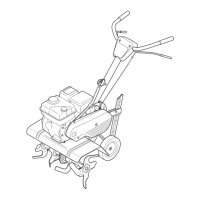
2. Placethehandleassemblyin positionbetweenthe handlemount-
ing brackets.See Figure3.
Handle Assembly.
Screws
7
J
Figure3
3. Lineup theholesinthehandlewiththe holesin the bracketand
securewiththehardwarepreviouslyremoved.