ATTACHING THE CONTROL ROD
1. Makesurethe handleassemblyisinthe highestposition.Referto
theOperationSection.
2. Removethehairpinclipsfromthecontrolrod,putthe rubber
washersin place.
3. Inserttheshorter,angledendof thecontrolrodthroughthe
indicatorbracketontheshiftcoverandsecureitwiththe previ-
ouslyremovedhairpinclip.SeeFigure4.
Rubb_
Washers
Figure4
4. Insertthelongerendof thecontrolrodthroughtheholeinthe
gearselectorhandleandsecurewitha cotterpin. SeeFigure5.
Gear Selector
Handle
Cotter Pin
Figure5
ATTACHING THE CLUTCH CABLE
1. Removethethreadedeyeboltandnut fromthecableend.
2. Routethe clutchcabletothe rightside ofthe handlemounting
bracketsandunderneaththehandle.
3. Pushthecablethroughthe holein the centerof the handleand
snapinthe plasticfitting.SeeFigure6.
Threaded Tube
Figure6
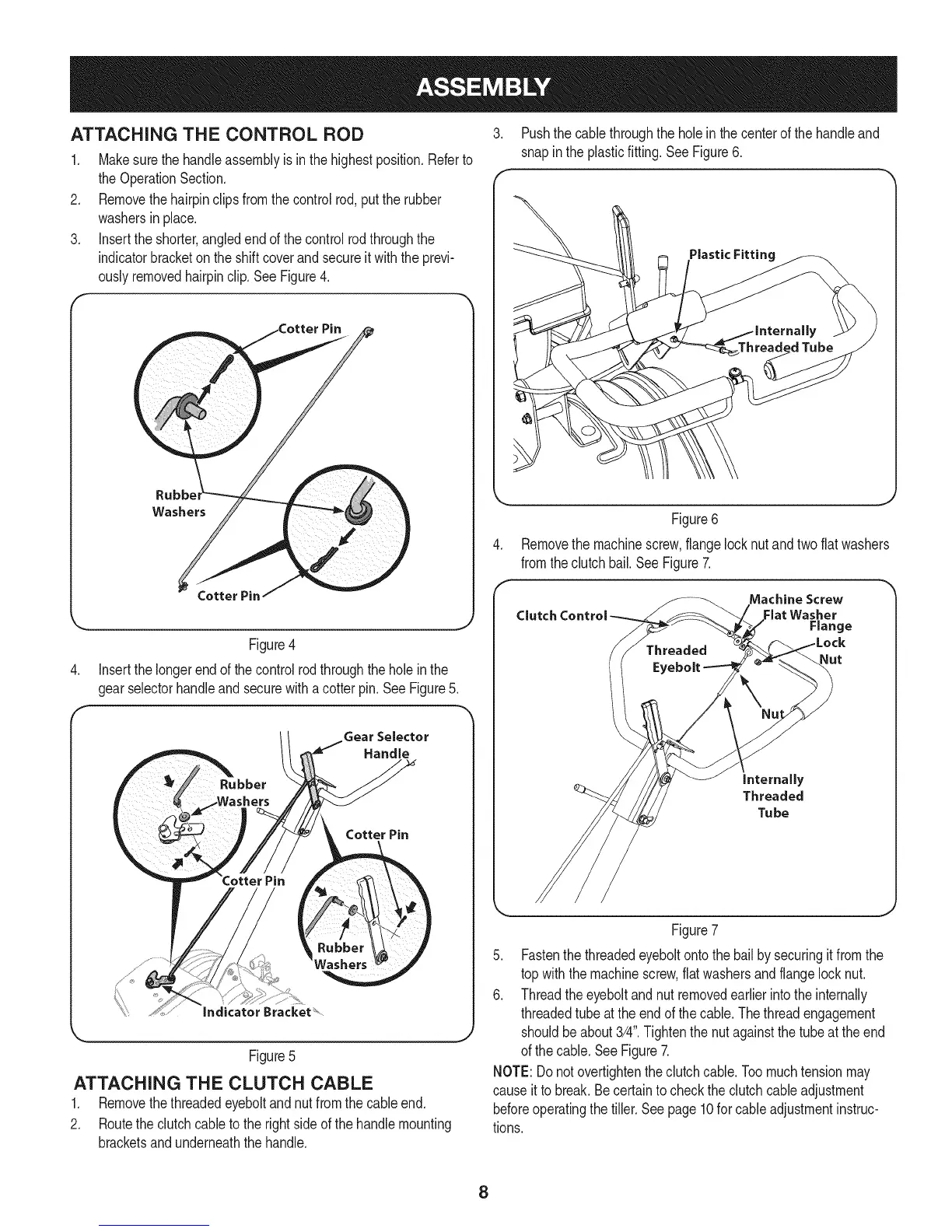
Removethe machinescrew,flangelocknutandtwoflatwashers
fromtheclutchbail.See Figure7.
Machine Screw
Clutch Control Flat Washer
Range
Nut
internally
Threaded
Tu be
Figure7
5. Fastenthe threadedeyeboltontothe bailby securingit fromthe
topwiththe machinescrew,flatwashersandflangelocknut.
6. Threadtheeyeboltandnut removedearlierintotheinternally
threadedtubeattheendof thecable.Thethreadengagement
shouldbeabout3/4".Tightenthenutagainstthe tubeat theend
ofthe cable.SeeFigure7.
NOTE:Donotovertightentheclutchcable.Toomuchtensionmay
causeitto break.Becertaintochecktheclutchcableadjustment
beforeoperatingthe tiller.Seepage10forcableadjustmentinstruc-
tions.
8