Page 2 of 62
Table of Contents
CAUTIONS & WARNINGS ........................................................................................................ 4
GENERAL INFORMATION ................................................................................................................. 5
Vender Safety Precautions ................................................................................................................ 5
Product Identification ....................................................................................................................... 5
CE Mark & IIA Declaration ................................................................................................................. 5
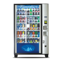
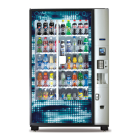
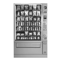
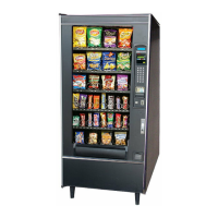
Physical Characteristics ..................................................................................................................... 5
INSTALLATION & SETUP .............................................................................................................................. 6
Receiving Inspection ......................................................................................................................... 6
Unpacking the Vender ....................................................................................................................... 6
Electrical Requirements .................................................................................................................... 7
Power Supply & Grounding Requirements ....................................................................................... 7
Prior to Initial Power Up .................................................................................................................... 8
Placing the Vender on Location ........................................................................................................ 9
Acceptable Ambient Operating Temperature Range ........................................................................ 9
Level the Vender ............................................................................................................................... 9
Locate the Vender ........................................................................................................................... 10
Install Price Labels ........................................................................................................................... 10
Install Product ID Cards ................................................................................................................... 10
Coin Changers and Other Accessories ............................................................................................. 10
Set Temperature Control ................................................................................................................ 11
Loading the Vender ......................................................................................................................... 11
Loading the Coin Changer Tubes ..................................................................................................... 11
R290 Service Notes…………………………………………………………………………………………………………………….12
Technical Work Process – R290………………………………………………………………………………………………….12
COMPONENTS ....................................................................................................................................................................13
Power Supply 24V 150W ................................................................................................................. 13
Power AC Distribution Box .............................................................................................................. 13
Vending Machine Controller & 5 Cabinet Controllers.....................................................................14
Keypad ............................................................................................................................................. 15
Digital Display .................................................................................................................................. 15
Delivery Port Assembly ................................................................................................................... 15
Shelf / Tray Assembly ...................................................................................................................... 15
Double Gate Assembly .................................................................................................................... 16
Slide / Pusher Assembly .................................................................................................................. 16
Delivery (Picker) Cup Assembly ....................................................................................................... 16
X Axis (Horizontal) ........................................................................................................................... 17
Y Axis (Vertical) ................................................................................................................................ 17
Belt Tensioning Adjustment Components....................................................................................... 17
Refrigeration System ....................................................................................................................... 17
Refrigeration Deck Clamp Assembly ............................................................................................... 17
Wiring notes .................................................................................................................................... 18
PROGRAMMING ......................................................................................................................................... 18
General ............................................................................................................................................ 18
Normal Mode .................................................................................................................................. 18
Service Mode................................................................................................................................... 18
External Menu Mode……………………………………………….…………………………………………………………………19
Initial Programming……………………………………………………………………………………………….…….…………….19
Service Mode……………………………………………………………..……………………………………………………….…..…19
Error Codes ...................................................................................................................................... 19
Tube Fill ............................................................................................................................................ 22
Test Modes....................................................................................................................................... 22
Password Entry ................................................................................................................................. 23
Price Program ................................................................................................................................... 23
Config Switches ................................................................................................................................ 24
 Loading...