Crestron DMPS-100/200/300-C/300-C-AEC DigitalMedia Presentation System
Operations Guide – DOC. 7219D DigitalMedia Presentation Systems: DMPS-100/200/300-C/300-C-AEC • 27
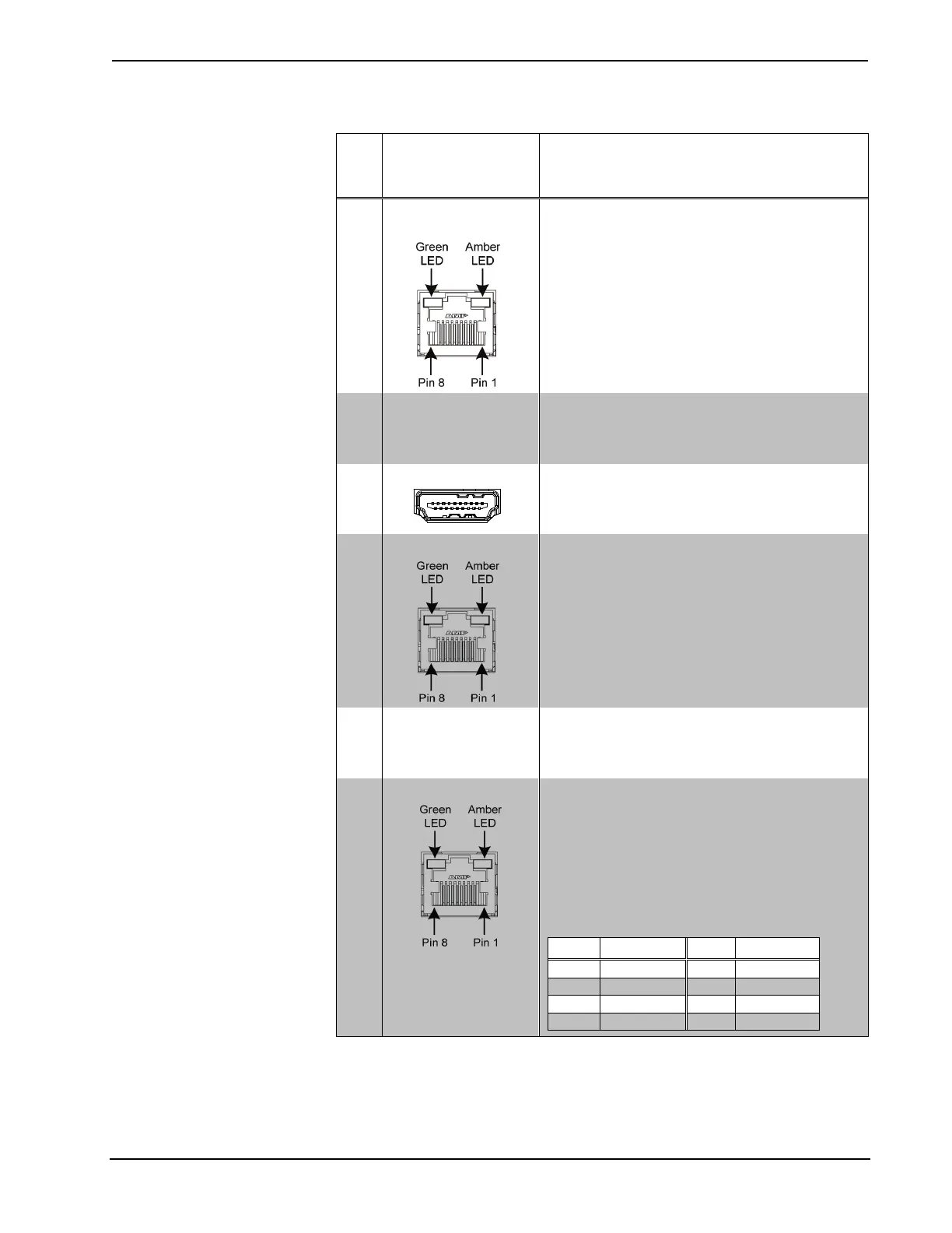
Connectors, Controls & Indicators (Continued)
# CONNECTORS
1
,
CONTROLS &
INDICATORS
DESCRIPTION
40
DM INPUT
Not present on DPMS-100, (1) for DMPS-200,
(2) for DMPS-300: 8-pin RJ-45 female, shielded;
DM 8G+ inputs, capable of supplying power over
DM
7
;
Connects to DM 8G+ output of a DM transmitter
or other DM device via CAT5e or Crestron
DM-CBL-8G cable
8
(2) LEDs, green LEDs indicate DM link status;
Amber LEDs indicate video and HDCP signal
presence, for each respective port
41 DM INPUT
PoDM LEDs
Not present on DPMS-100, (1) for DMPS-200,
(2) for DMPS-300: Green LEDs, indicate
upstream device is drawing power over DM for
each respective port
42 HDMI OUTPUT
(1) for DMPS-100 and DMPS-200,
(2) for DMPS-300: 19-pin Type A HDMI female,
digital video/audio outputs;
Signal types: HDMI, DVI
3
43 DM OUTPUT
(1) for DMPS-100 and DMPS-200,
(2) for DMPS-300: 8-pin RJ-45 female, shielded;
DM 8G+ outputs, capable of supplying power over
DM
7
;
Connects to DM 8G+ input of a DM receiver/room
controller or other DM device via CAT5e or
Crestron DM-CBL-8G cable
8
(2) LEDs, green LEDs indicate DM link status,
amber LEDs indicate video and HDCP signal
presence, for each respective port
44 DM OUTPUT
PoDM LEDs
(1) for DMPS-100 and DMPS-200,
(2) for DMPS-300: Green LEDs, indicate
downstream device is drawing power over DM for
each respective port
45 LAN
(1) 8-wire RJ-45 female;
10BASE-T/100BASE-TX/1000BASE-T Ethernet
port;
Right LED: green LED indicates Ethernet link
status
Left LED: bi-
color LED; amber blink indicates 1000
Mbps activity, green and amber blink mix indicates
100 Mbps activity, and green blink indicates 10
Mbps activity
1. Interface connectors for IR-SERIAL OUT, IR IN, AUD IN, INPUT, RELAY, MC-LN, NET,
SPEAKER OUTPUTS, PROG OUT, and AUX OUT ports are provided with the device.
2. Item(s) sold separately.
3. HDMI requires an appropriate adapter or interface cable to accommodate a DVI or DisplayPort
Multimode signal. CBL-HD-DVI interface cables available separately.
4. Deep Color and 3D video signals are only supported via HDMI inputs 1 and 2, and DM inputs 6 and 7.