40
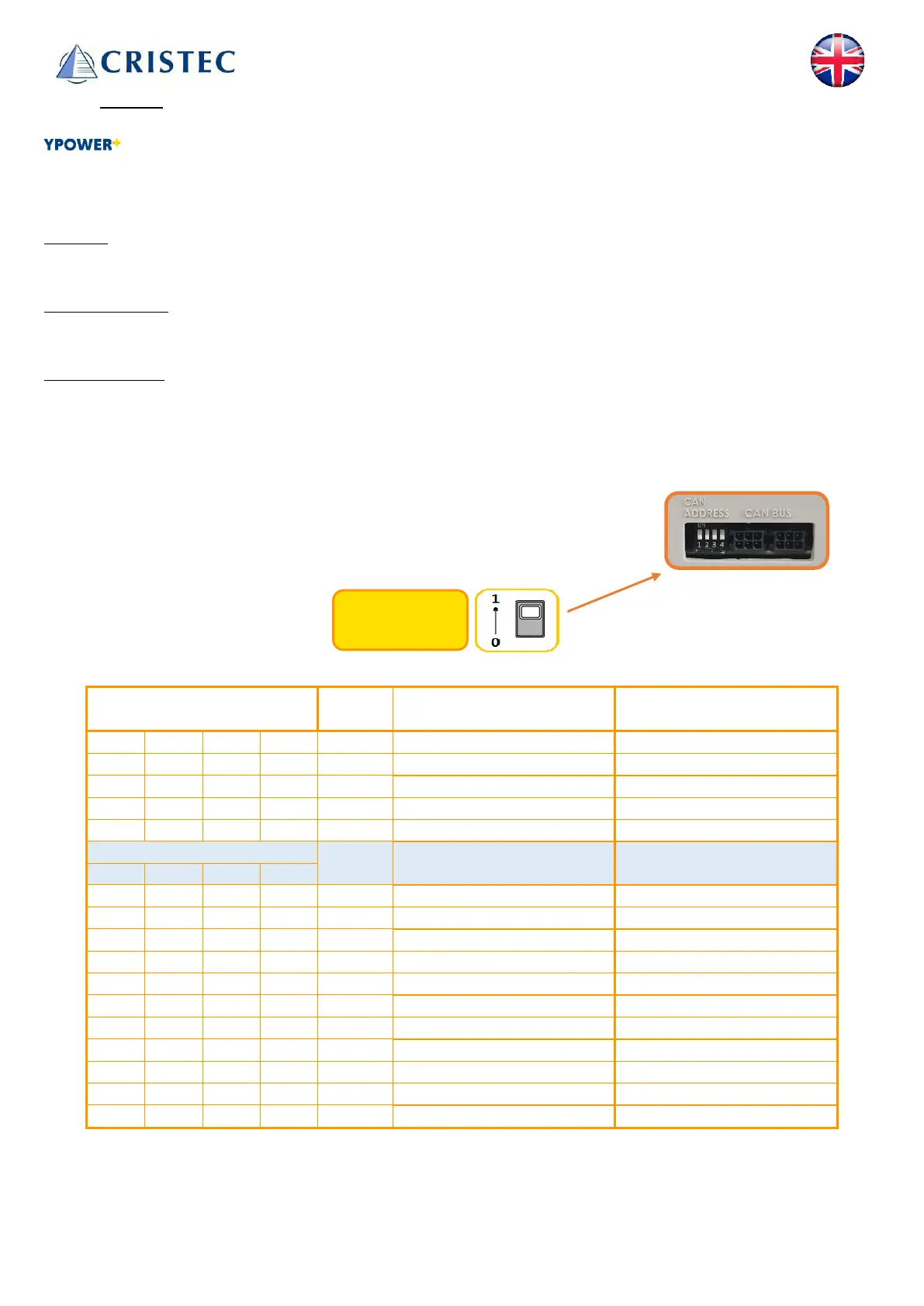
3.3.4 CANBUS
Chargers (excluding OEPL series) are fitted with two sockets compatible with Molex Microfit 3.0, 6-
pin connectors, part no. 43045-0600.
Bus-CAN documentation (hardware and software specifications) is available on request from CRISTEC.
Protocol
The CANBUS protocol can be selected using the CRISTEC CONNECT application (see 3.3.3).
CANBUS SUPPLY
BUS-CAN power must be supplied by other equipment, not by the charger itself.
Communication
Several equipments can be daisy chained on a CAN bus.
To enable communication between several devices, each entity must have a unique identifier (ID). This ID
must be selected using the 4 microswitches (1,2,3,4) available on the connection side.
Within a single CAN network, 4 sub-networks (A, B, C, D) can be defined.
This means that only the 4 sub-network entities can communicate with each
other.For example: Master A and Slaves A1, A2 & A3.
Switches settings ID
Sub-network
Factory settings (by default):
4 Slave A1 A
Dip-switches:
(1, 2, 3 et 4)