33
Remarks:
The chargers are working as soon as they are powered on (AC cable connected and
powered).
The chargers are stopped:
• as soon as they are no longer under AC voltage (power off delay of 20 seconds) and the output
DC network is disconnected for an activated standby mode.
• as soon as they are no longer under AC voltage (power off delay of 20 seconds) for deactivated
standby mode.
Indeed, the charger can still be active even if the AC input has been disconnected (see 3.4.3).
3.2.3 Battery cables
Disconnect batteries before any wiring and junction of the connector.
Please check the compatibility of voltage, current and setting according to the battery type before switching
ON the charger.
Checking of the charge voltage
Before connecting the batteries to the charger, first check their polarity.
Check also the battery voltage with a calibrated voltmeter. A too low voltage value on some types of
batteries shows irreversible damage and impossibility to recharge.
Any damage due to incorrect connections will be excluded from the warranty.
The table below defines the maximum battery cable cross-section allowable for the output connector:
Maximum allowable battery cable cross-section
12-20, 12-30, 24-15 16mm²
The installer should choose the type of cable (H07-VK, MX, etc.) according to the type of application and the
applicable standards.
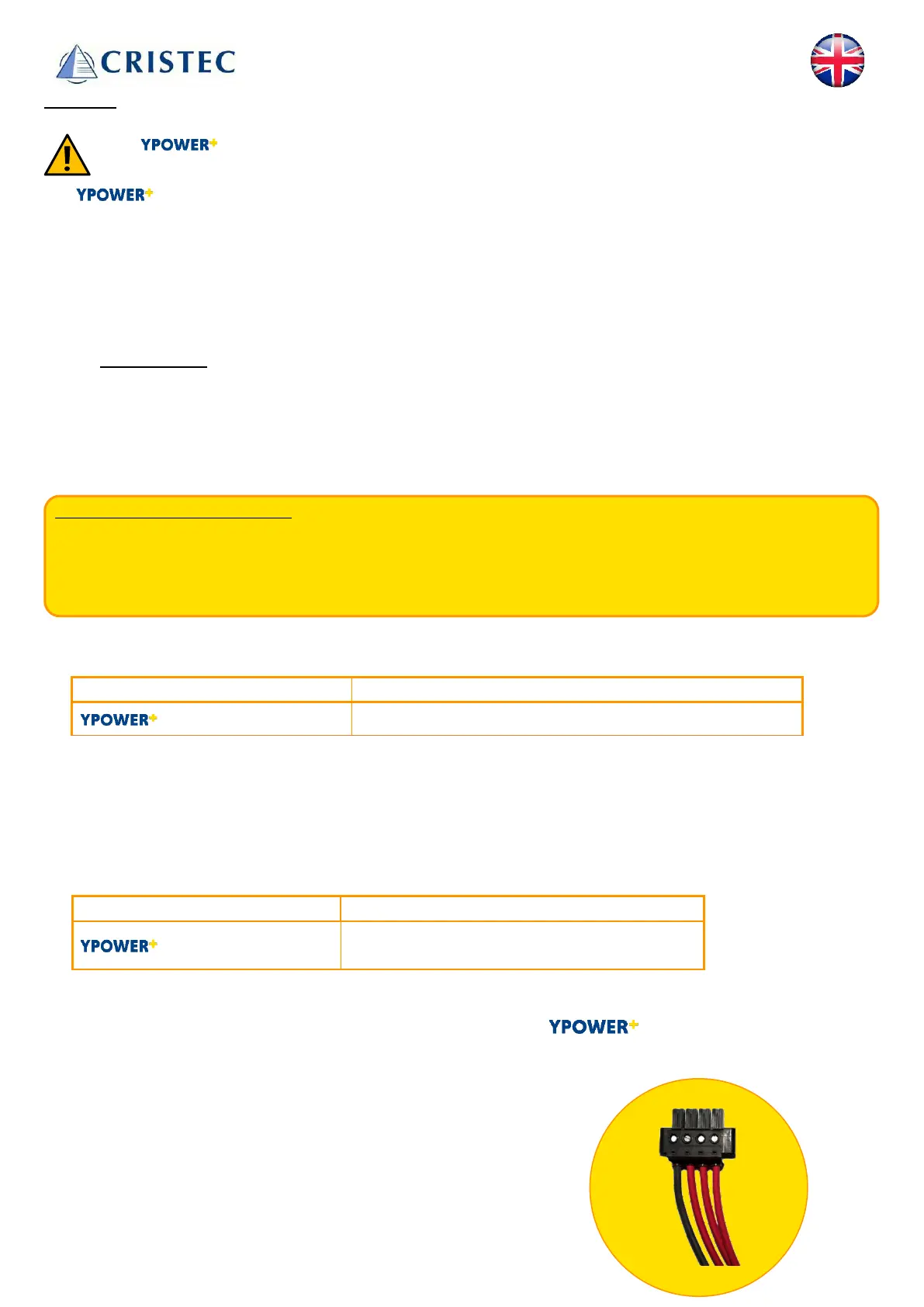
The DC outputs must use a PHOENIX CONTACT connector type. Unused terminals should remain
unconnected.
PHOENIX CONTACT connector reference
12-20, 12-30, 24-15
PC 16/4-STF-10,16 BK
(reference CRISTEC 30033787)
PHOENIX CONTACT connector junction
Connect from left to right: -BAT, +BAT E, + BAT 1 and +BAT 2 on all models
• - BAT (minus set of batteries)
• +BAT E (plus engine battery)
• +BAT 1 (plus battery set 1)
• +BAT 2 (plus battery set 2)