Page 82
DIALLER INSTALLATION
The dialler facility of the Power Wave controller has been designed to provide optimum flexibility in the way in which
alarm events are reported. This flexibility includes options for reporting to a central monitoring station using Contact
ID format, a domestic reporting option using alternating siren tones, a format for reporting alarms to an alpha numeric
pager and a powerful speech dialler.
In accordance with the statutory requirements of the Telephone permit standards we must bring the following points
to your attention;
In the event of any problem with this device, the user is to arrange with the installer of the device to make the neces-
sary repairs. Should the matter be reported to Telecom as a wiring fault, and the fault be proven to be due to the
alarm panel, a call out charge will be incurred.
Should the Power Wave control panel require relocation, the Telecom connection must be disconnected before the
power is disconnected. Similarly when reconnecting the dialler, it is necessary to power up the Power Wave before
connecting the dialler to the Telecom Network.
The transmit level from this device is set at a fixed level and because of this, there may be circumstances where
this device does not give its optimum performance. Before reporting such occurrences as faults, please check the
line with a standard Telstra telephone, and do not report a fault unless the telephone performance is impaired.
This automatic dialling equipment shall not be set up to make calls to the
Telecom "000" Emergency Service.
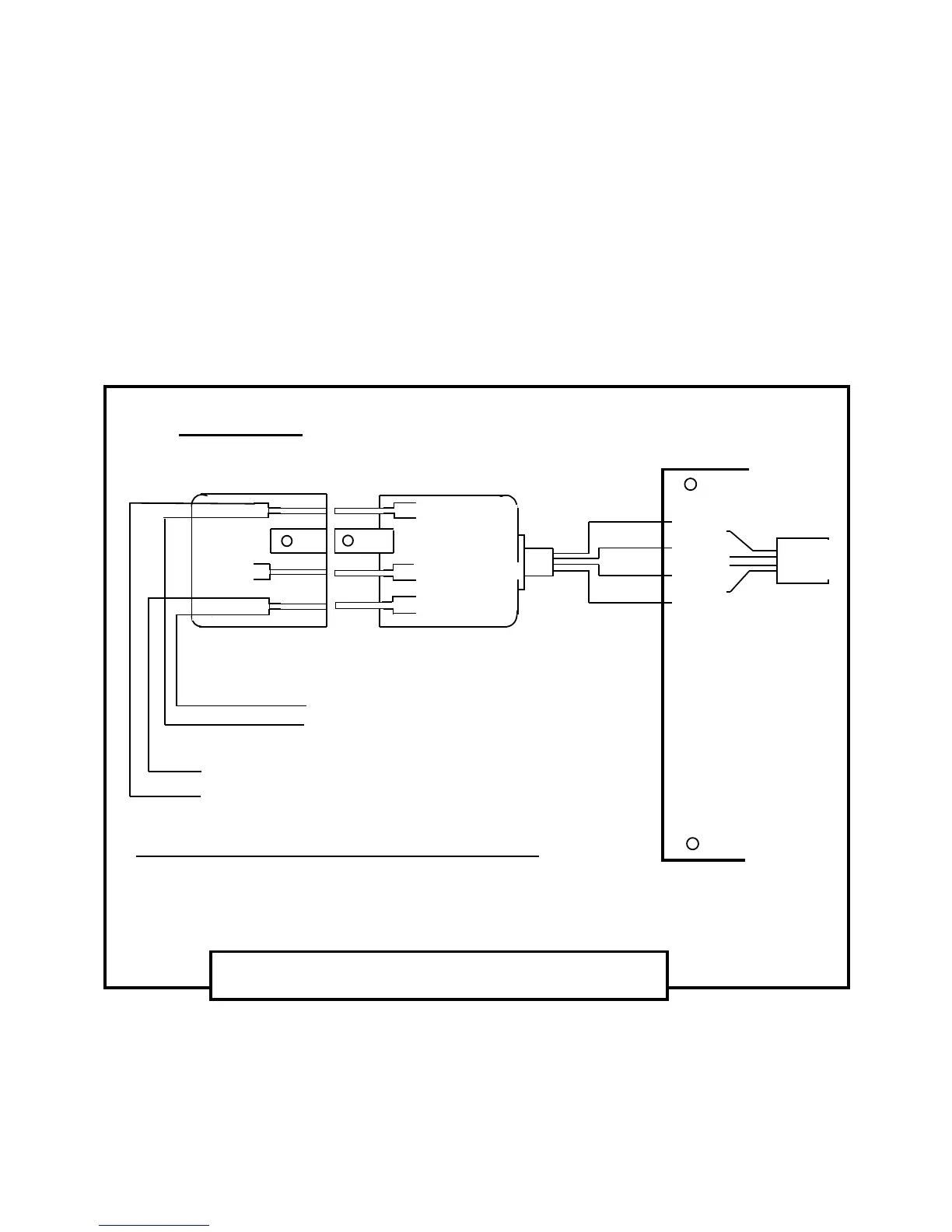
600 Series Plug
600 Series Wall Socket
Australian Mode - 3 Connection Diagram
Bottom View
Of The Mode 3 (Type 600) Plug And Wall Socket
Red
1
2
3 4
5
6
1
Red
Yellow
Black
5
2
3 4
6
POWER WAVE –8 CONTROLLER
Black
Red
Green
Yellow
Green
3 & 4 Not Connected
Black
Green
Yellow
TELEPHONE
LINE
( LINE IN )
TO INTERNAL
PHONES
( LINE OUT
)
Line Out
to Phones
Common (-)
to in/out
Line In
from Street
Phone
Socket
Mode 3 (Type 600) Plug And Wall Socket Wiring;
Terminal 6 = Tip-In = “ + ” side of Line-In from Street
Terminal 2 = Ring-In = “ - ” side of Line-In from Street
Terminal 5 = Tip-Out = “ + ” side of Line-Out to Int. Phones
Terminal 1 = Ring-Out = “ - ” side of Line-Out to Int. Phones