Page 9
Listn.
Data
Clock
Neg
Pos
Mode 3 (Type 600) Plug And Wall Socket Wiring;
Before calling Crow tech. Support or your supplier
Re: Phone Line or Dialler reported issues, please ensure
that the Mode-3 socket on the wall is wired as per below.
********** Observe Line In / Out Polarities **********
Terminal 6 = Tip-In = “ + ” side of Line-In from Street
Terminal 2 = Ring-In = “ - ” side of Line-In from Street
Terminal 5 = Tip-Out = “ + ” side of Line-Out to Int. Phones
Terminal 1 = Ring-Out = “
-
” side of Line-Out to Int. Phones
AC
Outputs
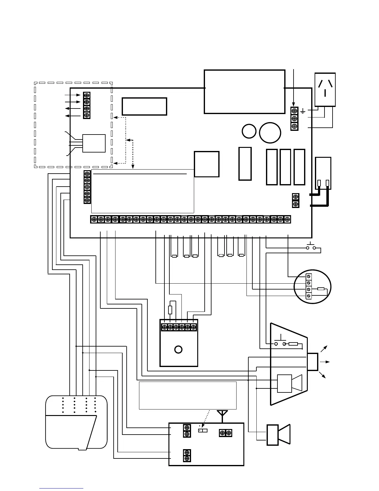
PCB WIRING INSTRUCTIONS
com
Battery
com
1&9
2&10
3&11
4&12
0V
Tmp
0V
12V
Heatsink
Serial Socket
Red
Blk
+
_
Optional (5th wire) Listen-in Keypad Connection
Passive Infra-
Red Detector
Tmp
Tmp
N/C
Com
0V
12V
2k2
+
_
Internal Alarm-Piezo
Crow Power
Wave-16 / Ver6.20
12v
0v
2k2
Latching Smoke Detector with
Normally Open Contacts
3A
F3
1.5A
F2
1.5A
F1
Telephone Line
Connections
0V
12
1 3 2 4 5 6 7 8
5&13
com
6&14
7&15
com
8&16
com
Key
12V
Ext Siren Box with
Siren/Strobe/Tamper.
+
_
+
_
2k2
Panel Tamper
AC
17V
2k2
2k2
2k2
2k2
2k2 2k2
16VAC
1.5Amp
Mains Earth
From Power
Pack
RJ11
Phone
Socket
In
Out
From ‘ + ’
Street ‘ - ’
To
‘ - ’
Phone
‘ + ’
Line Out (‘ + ’)
To Phones
( Tip-Out )
Line Out (‘ - ’)
To Phones
( Ring-Out )
Line In
From
Street
‘ + ’ Tip-In
‘ - ’ Ring-In
P/Wave-16
Keypad
Wireless Receiver “Bit” set jumper.
On = 24 Bit /
OFF = 40 Bit
( Leave OFF (on 1 pin only) for any type of
Crow Wireless Product, since Crow
products are 40 Bit setting compatible).
Pos
Neg
Clock
Data
Gnd Ant
RX-16 / 40
303 or 433 MHz
Wireless Receiver