Operating Instruction and Documentation
CSL640/641
- 54 – TES1518/E
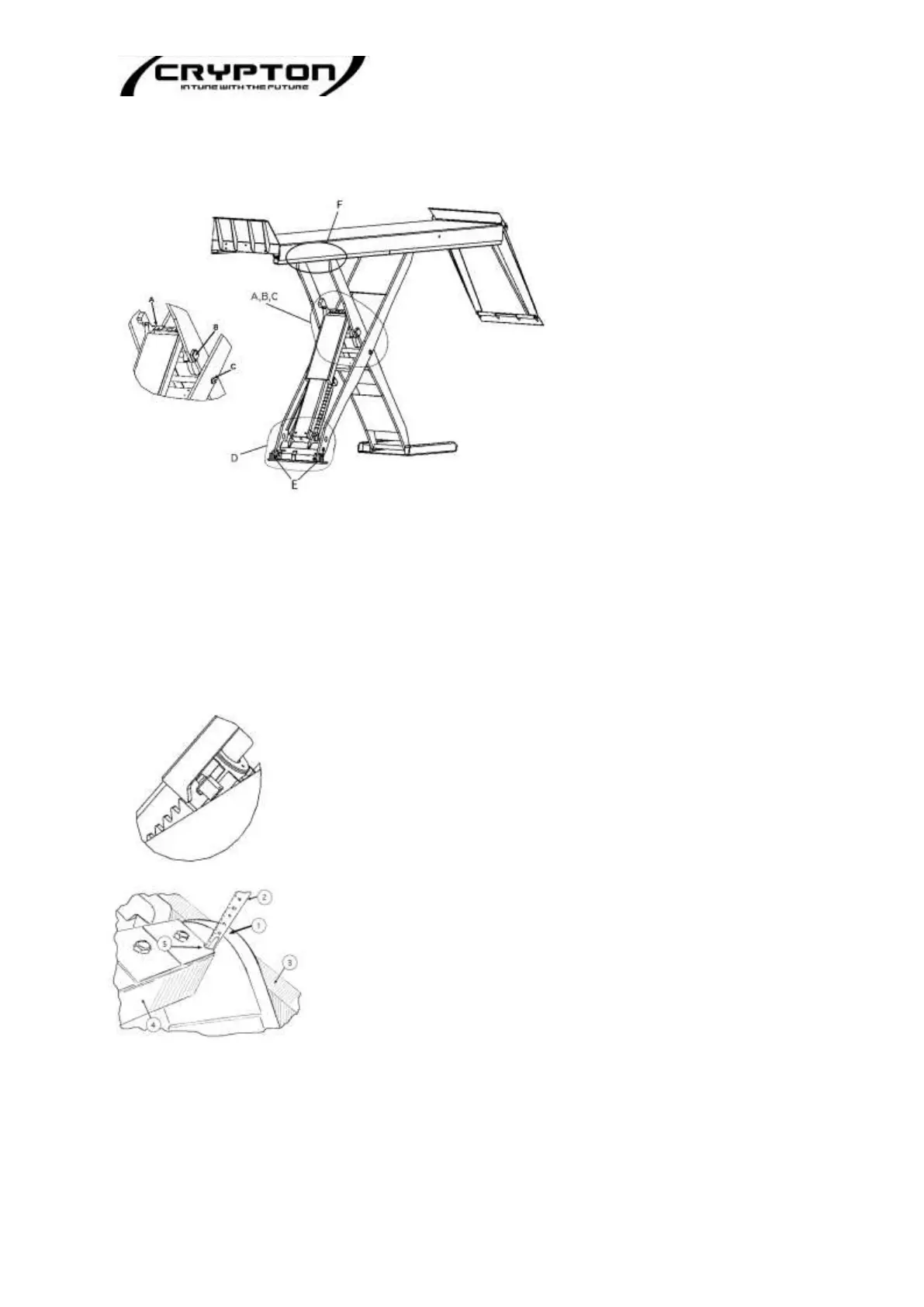
Pos. A - Piston-rod head and bearing bushings.
Pos. B - Bolt and bearing bushings of cylinder hinge plate.
Pos. C - Central bolt and bearing bushings.
Pos. D - Lower cylinder bolt and bearing bushings.
Pos. E - Lower fixed-bearing bolt and bearing bushings.
Pos. F - Upper fixed-bearing bolt and bearing bushings.
Pos. A - Piston-rod head and bearing bushings
Raise the lift slightly over the highest safety ratchet position.
Do NOT lower the lift in to the locked position.
Pic G: Position A (Piston-rod Head)
Pic H: Measuring points
Measuring the dimension between points 1 and 5. (see illustration)
1 - Highest measuring point at cylinder hinge plate
2 - Measuring tape
3 - Inner scissor arm
4 - Square piston-rod head
5 - lowest measuring point at leaf spring (or square head)
Pic F: Maintenance points