Operating Instruction and Documentation
CSL640/641
- 55 – TES1518/E
Make sure that leaf springs are properly tightened down. In some lift models the leaf
springs are fitted differently from the illustration. In such cases the measurement should
be taken from the top surface of the square head.
Check the following dimension:
The original dimension (lift in as new condition) between leaf spring and the highest point of the
cylinder hinge plate is:
Model CSL640/CSL641: Original dimension: 7,5 ± 2mm
If the measurement is taken directly from the square head, add 2mm to the
measured dimension to obtain the original dimension of the lift in as an new
condition.
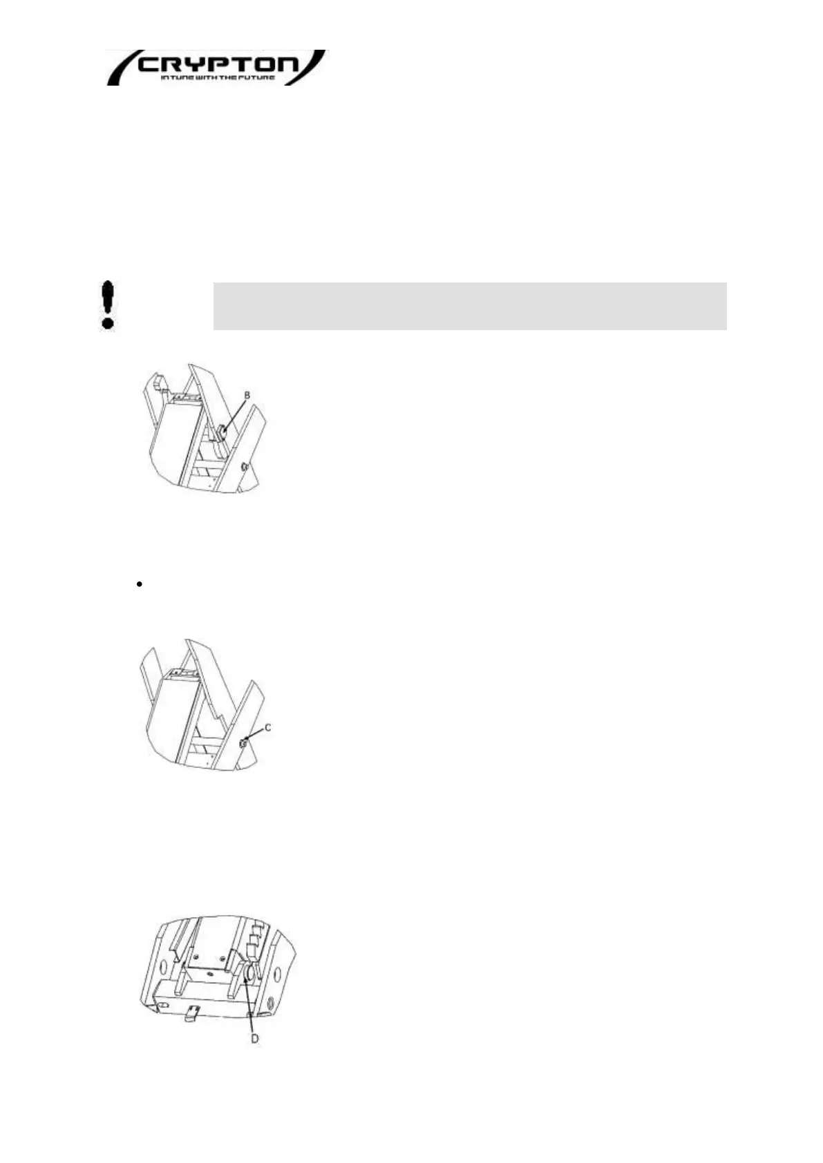
Pos. B - Bolt and bearing bushings of cylinder hinge plate
• Remove cover
• Clean area. Visually examine condition of bolt and bushings for wear. Do NOT move or
remove bolt.
• Both scissors need to be examined.
Repair or re-install back to original condition. Grease/oil as described in the lubrication
instructions
Pos. C - Central bolt and bearing bushings
• Remove castle-nut and split-pin
• Clean area. Visually examine the condition of bolt and bushings for wear. Do NOT move or
remove bolt.
• Both scissors need to be examined
• Repair or re-install back to original condition. Grease/oil as described in the
lubrication instructions.
Pos. D - Lower cylinder bolt and bearing bushings
• The condition of the bolt and bushings need to be visually examined for wear.