Do you have a question about the Culligan G1 Series and is the answer not in the manual?
Manual detailing the installation, operation, and service for Culligan G1 RO systems.
Covers electrical shock, injury, and equipment damage warnings.
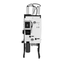
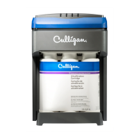
Highlights key features of the G1 RO system and GBE controller.
Details wall mounting and optional stand assembly.
Steps for installing pump/motor panel, fittings, and prefilter.
Critical steps for installing membranes and feed flow meter.
Illustrates the routing of tubing for the system.
Covers feed, concentrate, and product water connections.
Details for connecting the product water outlet.
Covers storage tank options and direct feed setup.
Covers language, serial number, and date/time settings.
Covers menu lockout, defaults, and flow meter overview.
Detailed steps for calibrating flow meters.
How to configure flow meter parameters.
Final system tests and checks before normal operation.
How to calculate and normalize product flow rates.
Covers low pressure and pretreatment lockout switches.
Procedure for setting the system's date and time.
Configuration for power on behavior and flush modes.
Setup for flow meters and other system accessories.
Setting power on mode and configuring flush modes.
Explains Startup, Standby, Quality, and Permeate flush types.
How to configure the selected flush modes.
Configuring startup, standby, and time trigger modes.
Configuring flow trigger, quality, and permeate flush modes.
Physical installation of the wireless remote unit.
Steps for setting up wireless communication.
Configuring wireless communication between GBE and remote.
Installing the modem into the controller or remote.
Configuring TDS probe and related settings.
Description and meaning of system error codes.
Table of problems, probable causes, and solutions.
Detailed explanations of system error codes.
Procedures for replacing prefilter cartridges and membranes.
Procedures for replacing the pump and motor.
Steps for cleaning the tank and RO elements.
Wiring diagram for the GBE RO controller.
Wiring diagram for 230V systems.
| Stages | 1 |
|---|---|
| Operating Temperature | 40 - 100 °F |
| Connections | 1" NPT |
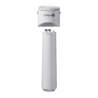
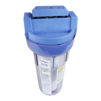
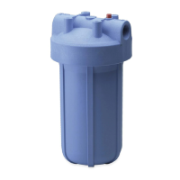
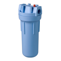
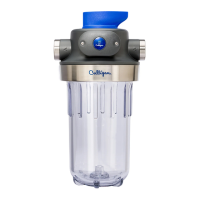
| Type | Whole House |
| Filter Life | 6 months |
| Reduces | Sediment |