18 Culligan® Series G1 Reverse Osmosis
18 Cat. No. 01021713
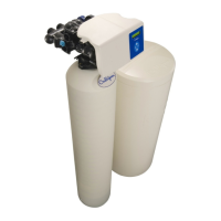
Pressurized Storage Tank
The product water can be stored in a pressurized storage tank with the reverse osmosis unit controlled by a pressure
switch. Use the same components used for direct feed (see Figure 16). The pressure switch needs to be wired to the con-
trol panel as a float switch (see Figure 57 on page 105 for G1 standard wiring). A pressurized water storage kit is avail-
able for the G1 under P/N D1013880 (110V) or P/N D1018976 (220V). Connect the product tubing to a bulkhead fitting at
the top of the storage tank such as P/N 01005095 (2-gallon), P/N 01004776 (3-gallon), or P/N 01004765 (9-gallon).
Non-Pressurized Product Water Storage Tank
Depending on the type of application, a level control may be required to turn the unit off when the storage tank is full.
Install the level control according to the instructions provided with the control. See “GBE RO Controller Basic sub-panel
wiring.” on page 105 for electrical connections.
NOTICE If a repressurization pump is used, an additional level control is recommended to prevent the
pump from running dry if the storage tank is empty.
To maintain high water quality, a hydrophilic air vent filter, vacuum breaker, pop-off valve, ultraviolet lamp, and pressure
relief valve may be required.
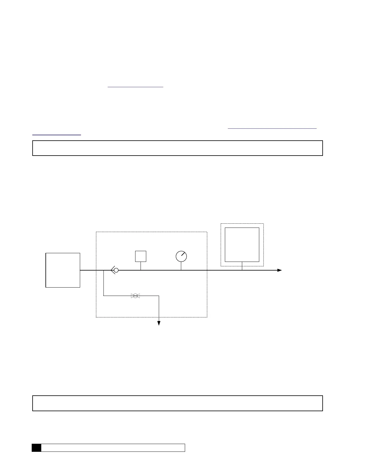
Direct Feed
If the product water is to be used directly, without storage, a few precautions are necessary to prevent damage to the
elements. Install a pressure gauge, pressure relief valve, and a normally-open (“dump”) solenoid in the product water
line as shown in Figure 16, or use pressurized storage kit (P/N D1013880). The pressure gauge will allow the operator to
monitor the product water pressure. The relief valve, which should be set to open at 40 psig, will prevent the product water
pressure from exceeding 40 psi. The dump solenoid will relieve all pressure when the unit is off.
52 6\VWHP
7R 6HUYLFH
7R 'UDLQ
3UHVVXUH *DXJH
69
3UHVVXUL]HG
6WRUDJH .LW
'
2SWLRQDO
3UHVVXUL]HG
6WRUDJH
7DQN
8VH RI 3UHVVXUL]HG 6WRUDJH7DQN UHTXLUHVXVH RI 3UHVVXUL]HG 6WRUDJH .LW'
:KHQ XVLQJ ' \RX PXVW VHWWKH IORDW VZLWFKHVWREH 1250$//< &/26('
36
&KHFN
9DOYH
3UHVVXUH 6ZLWFK
Figure 16. Direct feed connection.
Wire the direct feed/pressurized storage solenoid valve in parallel with the motor.
Valve SV4 closes when the RO pump runs; SV4 opens when the pump stops, allowing all membrane back proessure to
be relieved.
NOTICE Product back pressure will decrease the net pressure pushing water through the reverse osmosis
elements. Therefore, the flow of product water will decrease.
 Loading...