G1 RO Installation 11
Cat. No. 01021713
Plumbing Installation
Refer to the appropriate tubing installation instructions (Figure 11 on page 13 through Figure 15 on page 17) for
further information.
Feed Water Connections
Connect tubing to the Feed water inlet. Observe the following:
1. To minimize pressure loss, the tubing size should be at least 1/2”.
2. Install an optional pressure gauge (P/N D1006272) before the pre-filter. This allows you to measure the pres-
sure differential across the filter cartridge.
3. Install a tee, with a shutoff valve on the branch, before the feed flow meter to provide a connection for introduc-
ing cleaning solutions.
4. If necessary, install a pressure regulator (50 psi downstream max. setting) in the inlet plumbing, to assure con-
stant pressure and to prevent harmonic vibration.
5. Install a shutoff valve in the inlet plumbing to simplify maintenance and service.
6. If the feed water can be used for a short period, install bypass plumbing around the unit.
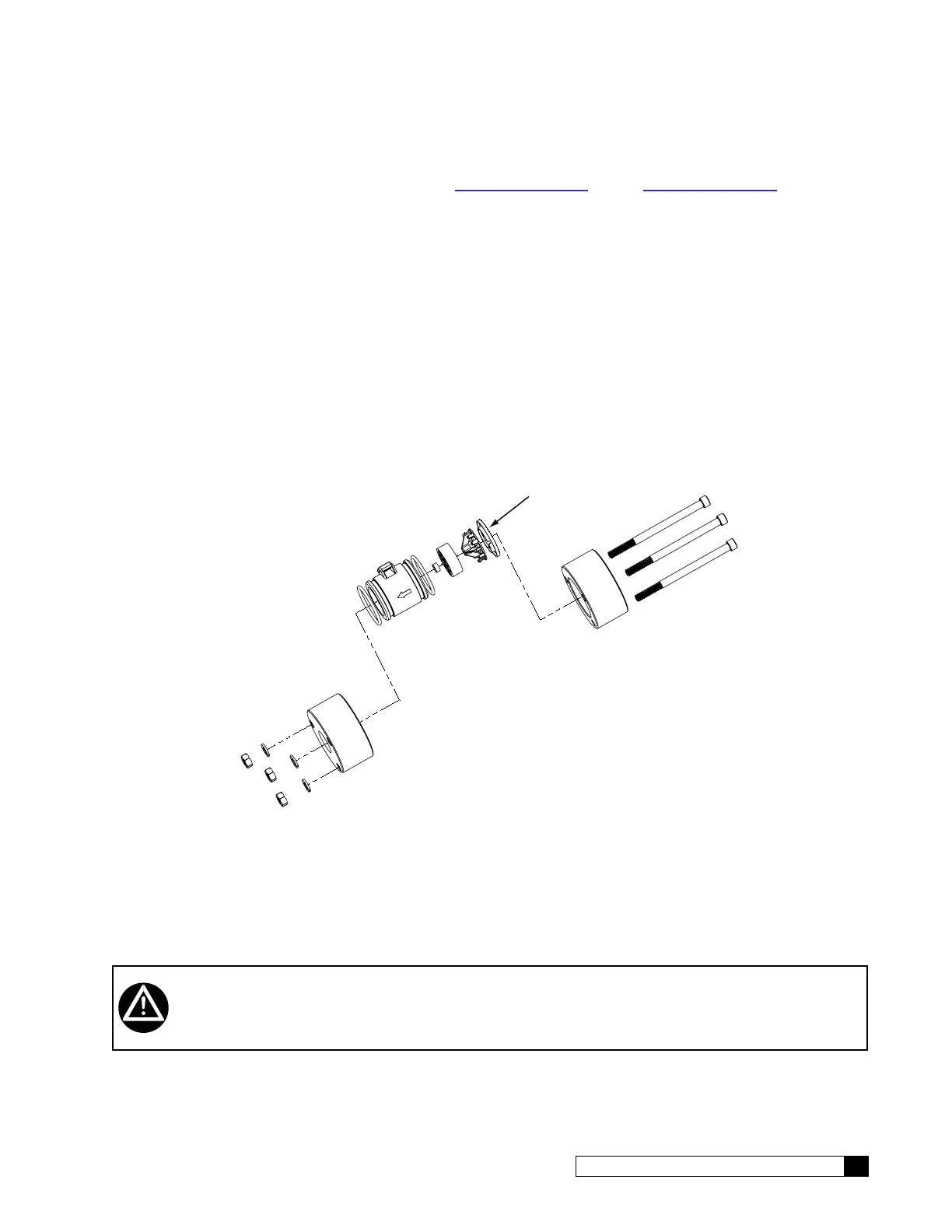
Figure 10. Feed meter and nozzle.
Concentrate Water Connections
1. Direct 3/8" piping to drain from the outlet of the unit.
2. To prevent siphoning of the water in the unit to drain, raise the concentrate piping above the level of the mod-
ules and provide an anti-siphon loop.
WARNING! An air gap must be provided between the end of the concentrate tubing and the drain
to prevent back-siphoning of drain contents.
 Loading...