G1 RO System Configurations 5
Cat. No. 01021713
G1 RO System Configurations
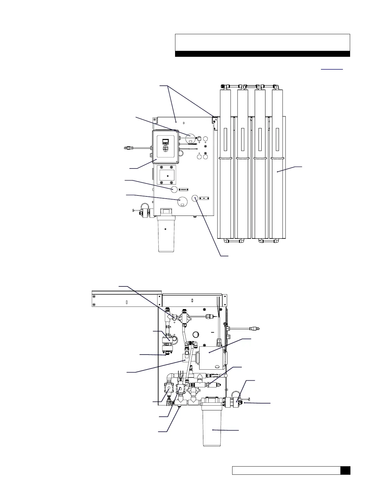
A G1-4L is pictured in Figure 1 and Figure 2. Width of membrane rack varies with model. See parts section on page 80
for a list of component part numbers.
MOUNTING BRACKETS
MEMBRANE FEED PRESSURE
INLET FEED PRESSURE
WASTE CONTROL
RECIRCULATION CONTROL
GBE RO CONTROLLER
MEMBRANES
Figure 1. G1 RO front view.
MOTOR
PUMP
PRODUCT FLOW METER
FEED FLOW METER
PREFILTER
INLET SOLENOID
FAST FLUSH SOLENOID
TDS SENSOR
PRESSURE SWITCH
PRODUCT WATER OUTLET
WASTE WATER OUTLET
FEED WATER INLET
Figure 2. G1 RO back view.
 Loading...