G1 RO Installation 9
Cat. No. 01021713
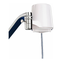
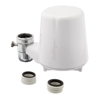
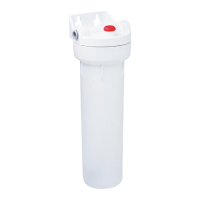
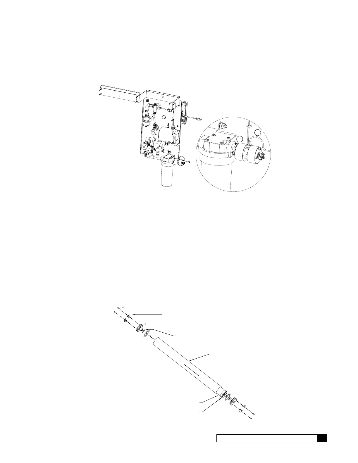
Feed Flow Meter
1. Install the feed flow meter on the prefilter.
2. Install the flow meter cable.
1
2
Figure 7. Feed flow meter installed on prefilter.
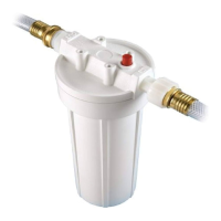
Membranes
Before mounting the membrane housings, the membranes must be inserted into the housings. Take care to not damage
the end cap O-rings or membrane brine seal.
The membranes are shipped in a sealed package. Use extreme caution when opening the package with a sharp instru-
ment. Any damage to the membrane can cause poor quality coming from the unit.
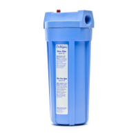
1. The membrane housings have directional arrows on them that indicate direction of flow. Install the membranes
in the direction of flow. Open the housing end opposite the direction of flow.
2. Remove the end caps from all vessels by removing the two Allen head screws that hold down the retaining
clips. The clips are pushed into an internal groove in the housing, so completely remove the screws so the clip
can be slid out of the groove. Note placement of the caps to assure reinstallation in the same orientation.
3. Check the O-ring seals on the membrane and end plug, and the membrane brine seal for damage. If an O-ring
is cut or crimped, it may cause high flow and poor quality. Replace any suspicious O-rings.
End Cap
Retaining Rings
O-Rings
FLOW
Membrane
Brine Seal
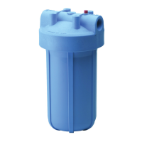
Housing
Figure 8. Membrane and its housing.
 Loading...