Caution! ESD Sensitive Components
Follow standard ESD and FOD controls to avoid damage to the internal components.
1. Remove the 15x 2-56 bolts using a #1 Philips screwdriver and remove base.
2. Insert a mini-PCIe card into slot 1 or 2. Use 2x 2mm screw with thread-locker, such as Loctite
222, to secure card to motherboard.
a. Mini-PCIe card slot 3 is reserved for installation at the factory.
3. Connect the corresponding cable from the mini-PCIe card to the expansion pins of the DuraCOR
311 I/O Board as required
a. A custom cable is required. See Integrating mini-PCIe Cards and Chapter 4 for available
I/O pins.
4. Close the unit and tighten screws to 34.4 in. oz. [0.24 Nm]. Use a thread-locker, such as Loctite
222.
Integrating Mini-PCIe Cards
To create a cable to bring out the I/O from the mini-PCIe cards through the circular connectors (J2-J4)
use the information in Chapter 4 for the available I/O. See Chapter 4, section Configurable I/O Internal
Connectors for manufacturer part number, mating connector, locations and pinouts. The configurable IO
lines do not contain any ESD protection.
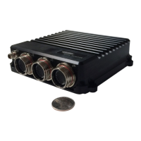
Figure 6: Card Slot Identification