Chapter 4 - Operational Description
This section describes the steps a user may have to perform during configuration of the DuraCOR 312. It
assumes that a user has already followed the quick start instructions in Chapter 2.It also describes the
interfaces that are available to the user.
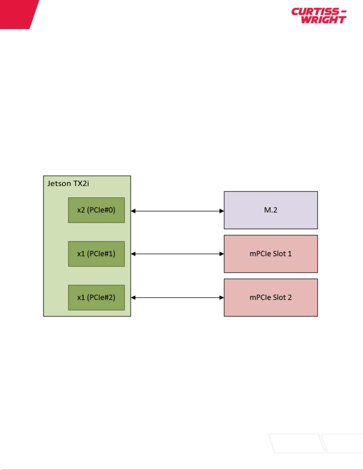
PCIe
The DuraCOR 312 contains PCIe Gen 2. The default configuration for the PCIe lanes from the Jetson
module is 1x2 (PCIe#0) and 2x1 (PCIe#1 and PCIe#2). PCIe#0 is routed to the M.2 slot. These lanes
can be used for the NVMe storage or additional PCIe based interfaces. PCIe#1 and PCIe#2 are routed to
the mPCIe slots 1 and 2 respectively. These are used for additional PCIe based interfaces.
Figure 7: PCIe Lane Mapping
Mini-PCIe Expansion
The DuraCOR 312 Mission Computer provides a powerful and flexible platform to integrate a variety of
devices based on Mini-PCIe. Without increasing the height of the base unit the DuraCOR 312 can
natively support up to two (2) Mini-PCIe cards (plus one M.2 module). Mini-PCIe devices may be PCIe or
USB 2.0 based interfaces. Typical devices offered in the Mini-PCIe form factor that can be easily
integrated into a DuraCOR 312 include:
Gigabit Ethernet
MIL-STD-1553