Chapter 1 - Introduction
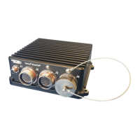
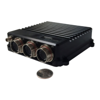
The DuraCOR 312 is an ultra-small form factor (USFF) modular mission computer built around the high-
performance, yet power efficient NVIDIA® Jetson™ industrial Jetson® TX2i “supercomputer-on-a
module” integrated in a miniature rugged chassis with MIL-grade high-density connectors. Combining
powerful NVIDIA Pascal™/CUDA-core GPU signal processing with 64-bit hex-core ARMv8
heterogeneous multi-processing (HMP) for size, weight, power and cost (SWaP-C) sensitive mobile,
airborne, ground, manned and unmanned vehicle and sensor platforms, the unit integrates a massively
parallel, many-core architecture boasting one of the highest computing FLOPS-per-watt architectures on
the market. Thanks to the unit’s Pascal GPU architecture (supporting Max-Q and Max-P dynamic energy
profiles), larger memory bandwidth, and support for CANbus, the DuraCOR 312 can deliver up to twice
the performance or power efficiency of TX1-based systems together with native vehicle bus interfaces.
The unit also deliver an unparalleled modular system design, boasting multiple Mini-PCIe I/O card slots,
high-speed M.2 internal storage, removable SATA Flash SSD capabilities, and an aerospace-grade
power supply supporting 50ms power hold-up in a fan-less IP67-rated mechanical package designed for
wide temperatures and harsh shock and vibration.
About This Document
Manual Organization
This manual provides functional and technical descriptions of the DuraCOR 312 hardware, instructions on
connecting the system to test equipment, connector descriptions and pinouts, and specifications.
Chapter 1 provides an introduction and function description of the DuraCOR 312
Chapter 2 provides a Quick start guide.
Chapter 3 contains connector pinouts for all connectors (external and internal).
Chapter 4 explains how to operate the DuraCOR 312. It describes the system connectors and
cables, and includes procedures for starting the system, installing and using Mini-PCIe IO cards,
etc.
Chapter 5 provides chassis specifications, dimensions, and mounting instructions. In addition, it
provides the technical and environmental specifications for the DuraCOR 312.
Chapter 6 provides troubleshooting instructions and technical support contact information
Chapter 7 provides additional contact information.
Definitions
Please refer to the Glossary at the end of this document for an explanation of terms.
Description of Safety Symbols
The following symbols are used in this manual to indicate important information and potentially dangerous
situations.