1. INSTALLATION AND USE
KPM216H
21-
RED
1
2
3
456
OPPOSITE VIEW SIDE
BLACK
BLACK
RED
OF
CABLE INSERTION
6 PIN (3X2)
FEMALE CONNECTO
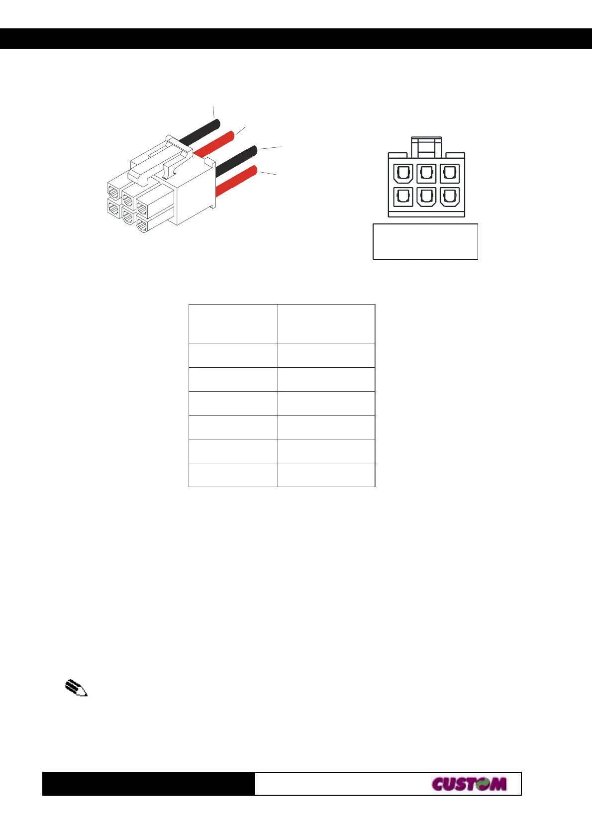
This picture shows the power supply cable included in the printer packaging :
The connector pin configuration of this cable is as follows:
elameF
rotcennoc
rolocelbaC
1.onniP
DER
2.onniP
detcennoctoN
3.onniP
DER
4.onniP
KCALB
5.onniP
detcennoctoN
6.onniP
KCALB
Note : The red cable is for +24 Vdc.
The black cable is for signal ground.
1.2 ADDITIONAL BRACKETS ASSEMBLING
Packing with the printer are supplied two additional fixing brackets. Assemble the brackets
(1)
to
printer set as shown in the fig. 1.3 and fig. 1.4.
(1)
N.B.: Before fixing the right lateral bracket (see fig. 1.2) remove the lateral
cover (refer to the opreations described in the 1.6.4 paragraph relevant to paper
jam).
(Fig.1.2)
 Loading...