11
Wiring diagram
◆ Wiring the master circuit and control circuit
Wire according to the standard connection diagram. On using the external sequence control, please
use small signal relay or double terminal relay to avoid relay terminal malfunction.
◆ Signal wire
The signal circuit uses either shielded pairs or twisted pairs, should be wired either using a wiring
duct separated from that for the power circuit, or with the wiring conduit isolated as much as
possible.
◆ Wiring between main circuit and motor
Connect the main circuit, by wiring according to the main circuit terminal connection diagram. Care
is required not to make a mistake when connecting the input and output terminals, lest it will cause
inverter damage. Specifications of main circuit path and NFB are as following:
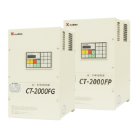
*CT2000F□
Voltage
(V)
Model NFB
(A)
Standard wiring
(mm
2
)
CT-2000FG-2-3A7 20 5.5
CT-2000FG-2-5A5 30 5.58
CT-2000FG-2-7A5 40 5.58
CT-2000F□-2-011 60 22
CT-2000F□-2-015 80 30
CT-2000F□-2-022 120 38
CT-2000F□-2-030 150 38100
CT-2000F□-2-037 200 38100
CT-2000F□-2-045 250 60100
CT-2000F□-2-055 300 100
CT-2000F□-2-075 400 100200
CT-2000F□-2-093 500 100200
CT-2000F□-2-112 500 100200
CT-2000FG-2-131 600 100200
220
CT-2000FG-2-150 600 200
Voltage
(V)
Model NFB
(A)
Standard wiring
(mm
2
)
CT-2000FG-4-3A7 10 3.55.5
CT-2000FG-4-5A5 15 3.55.5
CT-2000FG-4-7A5 20 5.5
CT-2000F□-4 -011 30 814
CT-2000F□-4-015 40 814
CT-2000F□-4-022 60 22
CT-2000F□-4-030 80 22
CT-2000F□-4-037 100 30
CT-2000F□-4-045 120 50
CT-2000F□-4-055 150 38100
CT-2000F□-4-075 200 38100
CT-2000F□-4-093 250 60100
CT-2000F□-4-112 300 60100
CT-2000F□-4-131 300 100
CT-2000FG-4-150 400 100200
CT-2000FG-4-188 400 100200
380
|
460
CT-2000FG-4-225 500 100200
No. Specification
G 150% load
P 120% load

 Loading...